Table of Contents
Advertisement
Quick Links
Advertisement
Table of Contents

Related Manuals for Brooks Guidance 5000


Summary of Contents for Brooks Guidance 5000
- Page 1 Guidance 5000 Controllers User Manual Part Number 614258 Revision A...
- Page 2 © 2024 Brooks Automation. All rights reserved. The information included in this manual is proprietary information of Brooks Automation, and is provided for the use of Brooks customers only and cannot be used for distribution, reproduction, or sale without the express written permission of Brooks Automation.
- Page 3 +86 21-5131-7066 +886 080-003-5556 (Toll Free) Taiwan +886 3-5525258 (Local) Korea 1800-5116 (Toll Free) +65 1-800-4-276657 (Toll Free) Singapore +65 6309 0701 (Local) General Emails Division Email Address Sales sales_preciseflex@brooksautomation.com Technical Support support_preciseflex@brooksautomation.com Technical Publications Technical.Publications@brooksautomation.com Copyright © 2024, Brooks Automation...
- Page 4 Guidance 5000 Controllers Part Number: 614258 Rev. A Revision History Revision Date Action Author Released manual at Rev. A to follow October 11, 149053 standard Brooks technical publication M. Ashenfelder 2023 styles. Copyright © 2024, Brooks Automation...
-
Page 5: Table Of Contents
Wiring Overview Motor Cables Motor Wiring Path Encoder Considerations Encoder Cables Encoder Wiring and Pin Assignments 4. Hardware Reference Guidance Controller Assemblies and Interfaces Guidance Controller Major Assemblies Connecting Power and Enabling Motor Power Controller Connectors Copyright © 2024, Brooks Automation... - Page 6 Yaskawa Sigma II/III Serial Absolute Encoder Nikon A/Sanyo Denki Serial Absolute Encoders EnDat / SII / BiSS Serial Absolute Encoders Appendices Appendix A: Product Specifications PreciseFlex Guidance 5000 Controller Specifications Appendix B: Environmental Specifications Appendix C: FAQ Copyright © 2024, Brooks Automation...
-
Page 7: Safety
1. Safety Safety Setup Brooks uses caution, warning, and danger labels to convey critical information required for the safe and proper operation of the hardware and software. Read and comply with all labels to prevent personal injury and damage to the equipment. -
Page 8: Explanation Of Hazards And Alerts
Notice indicates a situation or unsafe practice which, if not avoided, may result in equipment damage. The Notice signal word is white on blue background with no icon. Copyright © 2024, Brooks Automation... -
Page 9: Alert Example
Explanation of Hazards and Alerts Alert Example The following is an example of a Warning hazard alert. Number Description How to Avoid the Hazard Source of Hazard and Severity General Alert Icon Signal Word Type of Hazard Hazard Symbol(s) Copyright © 2024, Brooks Automation... -
Page 10: General Safety Considerations
Using parts with different inertial properties with the same robot application can cause the robot’s performance to decrease and potentially cause unplanned robot motion that could result in serious personal injury. Do not use unauthorized parts. Confirm that the correct robot application is being used. Copyright © 2024, Brooks Automation... - Page 11 Use of this product in a manner or for purposes other than for what it is intended may cause equipment damage or personal injury. Only use the product for its intended application. Do not modify this product beyond its original design. Always operate this product with the covers in place. Copyright © 2024, Brooks Automation...
-
Page 12: Mechanical Hazards
Vibration indicates a serious problem. Immediately remove power. Before energizing, ensure the robot is bolted to a rigid metal chamber or stand. Electrical Hazards Refer to the specifications of the Guidance Controller Quick Start Guide for the electrical power. Copyright © 2024, Brooks Automation... - Page 13 Improper handling of the power source or connecting devices may cause component damage or equipment fire. Connect the system to an appropriate electrical supply. Turn off the power before servicing the unit. Turn off the power before disconnecting the cables. Copyright © 2024, Brooks Automation...
-
Page 14: Emergency Stop Circuit (E-Stop)
Do not override or bypass the emergency stop circuit. Recycling and Hazardous Materials Brooks Automation complies with the EU Directive 2002/96/EU Waste Electrical and Electronic Equipment (WEEE). The end user must responsibly dispose of the product and its components when disposal is required. -
Page 15: Introduction To The Hardware
The Guidance 5000 Controller is the third generation of the smallest, most economical family of PreciseFlex motion controllers. This new generation of controllers supports up to 200 W motors and includes standard features such as a manual control pendant interface, dual E-Stop signal inputs, and an RS-485 communication interface. - Page 16 For example a four- axis robot can be coordinated with a two-axis robot. The Guidance 5000 can be run as a standalone robot controller or it can be a slave controller in a network of controllers where the master is a Guidance 6000 or another Guidance 5000.
-
Page 17: System Diagram
2. Introduction to the Hardware Part Number: 614258 Rev. A System Overview System Diagram The Guidance 5000 system diagram is shown in Figure 2-1. The controller consists of a CPU board (LVCPU) and a motor power amplifier board (LVAMP4A). Figure 2-1: Guidance 5000 System Diagram This unit can operate as a standalone controller or as a master or slave within a controller network. -
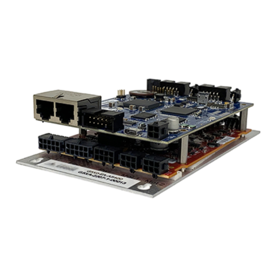
Page 18: System Components
AC line power is on. The following is a picture of the Guidance 5000, which includes the LVAMP4A motor power amplifier (lower board) that has Amp Micro MATE-N-LOK connectors. -
Page 19: Low-Voltage Power Supply And Guidance Controllers
2 Amps. For applications using remote IO, Ethernet cameras or several motor brakes, Brooks recommends a total of 4 Amps. This voltage may be supplied by a user power supply or a 24VDC power supply may be purchased from Brooks. -
Page 20: Remote Front Panel, E-Stop Box And Manual Control Pendant
Remote Front Panel interface signals. For an E-Stop button without a remote front panel, Brooks sells an E-Stop Box with a connector pigtail that plugs into the Remote Front Panel connector. For a Manual Control Pendant (MCP) that can be carried around the workcell, Brooks offers two hardware MCPs. -
Page 21: Remote Io Module
The Enhanced RIO module is shown in Figure 2-5. The RIO contains unshielded 24VDC signals and pins. This product is intended to be mounted in a cabinet or machine chassis that is not accessible when power is turned on. Copyright © 2024, Brooks Automation... -
Page 22: Machine Vision Software And Cameras
Status LED, the "Power State DOUT" (DataID 235) must be set equal to the signal's channel number. The execution conditions that are indicated by the LED and the output signal (if configured) are described in Table 2-1. Copyright © 2024, Brooks Automation... - Page 23 The processor is overheating, motor power is off and you Blinks eight times have 5 minutes to save any programs or data. After 5 CPU overheating per second minutes, the processor will shut down and needs to be rebooted. Copyright © 2024, Brooks Automation...
-
Page 24: Machine Safety
Machine Safety Voltage and Power Considerations The Guidance 5000 controllers require two DC power supplies: a 24VDC power supply for the logic and user IO, and a motor power supply. The motor power supply must provide the controller with a voltage between 12VDC and 48VDC. -
Page 25: Safety Standards Reference Material
EN 65000-4-2 Electrostatic Discharge (8 KV air, 6 KV contact) EN 65000-4-3 Radiated Electromagnetic Field Immunity (3 V/m, 27-500 MHz) EN 65000-4-4 Electrical Fast Transient/Burst Immunity (2 KV) EN 65000-4-5 Surge Immunity Test (1 KV differential, 2 KV common mode) Copyright © 2024, Brooks Automation... -
Page 26: Moving Machine Safety
E-Stop circuitry. See the ANSI/RIA R15.06 Safety Standard for Industrial Robots or EN ISO 10218-2-2007, Robots for Industrial Environments, Safety Requirements, for information on recommended safe operating practices and enclosure design for robots of various sizes and payloads. Copyright © 2024, Brooks Automation... -
Page 27: Installation Information
3. Installation Information Heat Sinking and Mounting The Guidance 5000 Controllers have a very small footprint but can control a substantial amount of motor power. For reliable operation, it is important that these controllers be properly mounted on a heat sink and cooled to dissipate the heat generated by the controller’s power devices and high performance ICs. - Page 28 These temperatures can be read via the Web interface Control Panels > System Information > System Console > Amp Temp. NOTE: For long-term reliable operation, the CPU temperature should be 80 C or lower and the amplifier temperatures should be 80 C or lower. Copyright © 2024, Brooks Automation...
-
Page 29: Recommended Motor And Encoder Wiring
Fortunately, since the Guidance 5000 is limited to relatively low motor voltages, the problem of induced ground bounces is significantly mitigated. However, because other devices in the system may generate similar electrical noise, it is good practice to employ wiring methods that safeguard against such problems. -
Page 30: Motor Wiring Path
Figure 3-2 illustrates how the motor cable should be wired. The shield around the motor cable is optional, but a good practice to follow. Copyright © 2024, Brooks Automation... -
Page 31: Encoder Considerations
One of the twisted pairs should be used for power and ground, one pair for A+ & A-, one pair for B+ & B-, and one pair for Z+ & Z-. (See the next section.) Connect the shield to one of the ground Copyright © 2024, Brooks Automation... -
Page 32: Encoder Wiring And Pin Assignments
Encoder Wiring and Pin Assignments Each encoder connector on the Guidance 5000 provides pins for interfacing to a differential incremental encoder or an absolute encoder. This interface can also be utilized to connect to single- ended encoders. However, it is always best to select an encoder with differential signals for the greatest noise immunity. -
Page 33: Hardware Reference
Guidance Controller Assemblies and Interfaces 4. Hardware Reference Guidance Controller Assemblies and Interfaces Guidance Controller Major Assemblies The Guidance 5000 controllers consist of two printed circuit board assemblies and a heat spreader mounting plate. These components are illustrated in Figure 4-1. -
Page 34: Connecting Power And Enabling Motor Power
Motor Amplifier Board to the mounting surface. Connecting Power and Enabling Motor Power The Guidance 5000 Controller, motor power supply, and 24VDC logic power supply should be connected as shown in Figure 4-2. - Page 35 Figure 4-2: Optional Connections Electrical Shock Hazard Contact with electrical power can cause serious injury or death. The Guidance 5000 is powered by 24VDC and can contain voltages up to 48VDC to drive the motors. Mount this product in a cabinet or machine chassis that is not accessible when AC line power is on.
- Page 36 In addition to the logic and motor power supplies, when certain types of absolute encoders are utilized, battery power must be supplied to the encoders when the controller is powered down in order for the encoders to retain their multiple turn counters. In this case, an external battery should Copyright © 2024, Brooks Automation...
-
Page 37: Controller Connectors
Controller Connectors In addition to providing interfaces for up to four motors and encoders, the Guidance 5000 provide extensive communication services. The connectors for each of these interfaces are described in detail in... - Page 38 Status LED and Status Output Signal RS-485 RS-232 Motor 3 Motor 4 Brake Release Encoder 3 Encoder 4 In the following sections, the pin-outs for each of the connectors plus the part numbers for the mating plugs are presented. Copyright © 2024, Brooks Automation...
- Page 39 Table 4-3: Pin Out Description BRAKE. Connect this signal to GND to release the brakes. User Plug Part AMP 794617-2. Use an AMP 91501-1 hand tool and AMP 794610-1 sockets for wiring to the plug. Copyright © 2024, Brooks Automation...
- Page 40 Guidance Controller Assemblies and Part Number: 614258 Rev. A Interfaces Digital Input and Output Signals The Guidance 5000 provides four general-purpose optically isolated digital-input signals and four general-purpose optically isolated digital-output signals. These signals are presented in a single ten-pin IDC connector (Figure 4-6).
- Page 41 (Figure 4-10), the external equipment must pull-down the output pin to ground and the controller pulls this pin to 24VDC when the signal is asserted as true. This configuration is compatible with "sinking" (NPN) devices. Copyright © 2024, Brooks Automation...
- Page 42 Digital Input 2 10003 Digital Input 3 10004 Digital Input 4 User Plug AMP 1658622-1 or Molex 22-55-2101 or 90142-0010. For the Molex plug, use Molex Part No sockets 16-02-0103 or 90119-2110 and Molex crimp tool 63811-5000. Copyright © 2024, Brooks Automation...
- Page 43 Guidance Controller Assemblies and Interfaces Encoder Interfaces Guidance 5000 controllers are equipped with 1, 2, 3, or 4 encoder interfaces that match the number of integrated motor drives. The signals for each of the encoder interfaces of the G5000 and the 3rd...
- Page 44 Motor Interfaces Guidance 5000 controllers are equipped with 1, 2, 3, or 4 motor drives. The motor interface for each drive of the G5000 is provided in a 6-pin AMP 3-794618-6 connector that mates with an AMP 794617-6 plug (Figure 4-13).
- Page 45 Brake power return. Set to ground to energize (release) brakes otherwise 24VDC. Motor frame ground/cable shield Motor phase U User Plug Part AMP 794617-6. Use an AMP 91501-1 hand tool and AMP 794610-1 sockets for wiring to the plug. Copyright © 2024, Brooks Automation...
- Page 46 The pinout for the G5000 Motor Power Input Connector is described in Table 4-7. Copyright © 2024, Brooks Automation...
- Page 47 AC line voltage. In the case of the Guidance 5000 controllers, the Motor Power On connector provides a signal that switches to ground when motor power is enabled and is automatically opened when an E-Stop or other condition occurs that requires the motors to be disabled.
- Page 48 Depending upon the type of jumper, there may be two or three jumper posts. Posts are tied (shorted) together using black jumper plugs. Copyright © 2024, Brooks Automation...
- Page 49 The locations of each set of jumpers are illustrated in Figure 4-17 and defined in Table 4-9 identified by stenciled labels on the surface of the LVCPU board. Figure 4-17: Jumper Locations Table 4-9: Processor Board Jumpers Number Explanation J7 Master/Slave J8 System Reset Copyright © 2024, Brooks Automation...
- Page 50 Master mode. For Slave mode install jumper on J7 Master / Slave Slave mode. Install Jumper J7-2 to pins 1 & 2. J7-3 for Master mode NOTE: As shipped from the factory, this jumper is not installed and indicates Master mode. Copyright © 2024, Brooks Automation...
- Page 51 (The controller is shipped with these jumpers installed.) 1-2, 3-4 The pinout for the Remote Front Panel Connector is described in Table 4-11. Copyright © 2024, Brooks Automation...
- Page 52 RS-485 connector instead of the three- pin Micro MATE-N-LOK connector. This option was developed to permit the PreciseFlex 400 robot to support a bar code reader that is mounted on the robot's gripper. See Table 4-12. Copyright © 2024, Brooks Automation...
- Page 53 Micro MATE-N-LOK. This option was developed to permit the PreciseFlex 400 robot to support a bar code reader that is mounted on the robot's gripper. This interface is provided in a ten-pin IDC connector (see Figure 4-20 Table 4-13). Copyright © 2024, Brooks Automation...
- Page 54 Signals. If an external LED is not required, this output signal can be utilized as an extra general digital output. This additional digital output signal is provided via a two-pin AMP 3-794620-2 connector. The mating plug is an AMP 794617-2. See Figure 4-21. Copyright © 2024, Brooks Automation...
- Page 55 4-14. Table 4-14: Pinout & Signal Number GPL Signal Description Number Digital Output 8 User Plug AMP 794617-2. Use an AMP 91501-1 hand tool and AMP 794610-1 Part No sockets for wiring to the plug. Copyright © 2024, Brooks Automation...
- Page 56 Mount this product in a cabinet or machine chassis that is not accessible when AC line power is turned on Figure 4-23: Mean Well P/N PPS-125-24 Power Supply Copyright © 2024, Brooks Automation...
- Page 57 47 - 63 Hz Output voltage 24 VDC Output power 125 watts Operating temperature 0 - 40 deg C Storage temperature -20 - 85 deg C Dimensions 127 x 76.2 x 34.6 mm PreciseFlex Part Number PS10-EP-00125 Copyright © 2024, Brooks Automation...
- Page 58 Controller Software section of the PreciseFlex Library. Table 5-1shows the wiring instructions for the Encoder Connectors. Table 5-1: Encoder Connectors Encoder Connector Pin Wire Color Signal Name G5000 Connector Pin BATTERY+ PINK BATTERY - GREEN BLUE Copyright © 2024, Brooks Automation...
- Page 59 Connector. Please see the information on that connector for detailed pinout and plug types. Table contains information on the required battery power. Table 5-3: External Battery Specification Maximum voltage 4.75 V Typical voltage 3.6 V Alarm trigger voltage 3.1 V Current for each encoder 3.6 uA Copyright © 2024, Brooks Automation...
- Page 60 Connector. Please see the information on that connector for detailed pinout and plug types. Table contains information on the required battery power. Table 5-5: External Battery Specification Maximum voltage 4.75V Typical voltage 3.6V Alarm trigger voltage 3.1V Copyright © 2024, Brooks Automation...
- Page 61 BATTERY - LIGHT BLUE DATA+ WHITE/LIGHT BLUE DATA - Table 5-7 shows the wiring instructions for the Motor Power Connectors: Table 5-7: Motor Power Connectors Motor Connector Pin Wire Color Signal Name G5000 Connector Pin WHITE Copyright © 2024, Brooks Automation...
- Page 62 16-bit "turns count" battery backed-up register for a total of 33-bits of encoder position information. Due to the additional capabilities needed to process the absolute encoder signal, these encoders may require the "Enhanced" versions of the Guidance Controllers. Contact Brooks at support_ preciseflex@brooksautomation.com for the current hardware requirements for interfacing to these types of encoders.
- Page 63 This section provides wiring instructions for motors equipped with one of the following types of serial absolute encoders: Heidenhain EQN1135, EnDat 2.2, 23-bits/revolution, 12-bit multiple turns counter Heidenhain EQI1130, EnDat 2.1, 18-bits/revolution, 12-bit multiple turns counter Copyright © 2024, Brooks Automation...
- Page 64 In general, these encoder types do not require a battery backup source to maintain their multiple turns counter. Due to the additional capabilities needed to process the absolute encoder signal, these encoders may require the "Enhanced" versions of the Guidance Controllers. Contact Brooks at support_ preciseflex@brooksautomation.com for the current hardware requirements for interfacing to these types of encoders.
- Page 65 Part Number: 614258 Rev. A Appendix A: Product Specifications Appendices Appendix A: Product Specifications PreciseFlex Guidance 5000 Controller Specifications Table 6-1 contains the specifications for the various models of the PreciseFlex G5000 Controller. "S" indicates a standard feature "O" indicates an available optional feature "-"...
- Page 66 Provides controller with a complete set of image- processing, measurement, inspection and finder tools. A Machine Vision powerful patented Object Locator finds parts in any orientation and at different scales within milliseconds. Motion Control Copyright © 2024, Brooks Automation...
- Page 67 Control Signals Signal lines shared among several functions. Up to 1 A at 24 VDC available for Brake Signals releasing motor brakes Communications Interfaces Serial RS-232 port with software (no Communication hardware) flow control Copyright © 2024, Brooks Automation...
- Page 68 PreciseFlex RIO modules or 3rd party MODBUS/TCP devices RS-485 multi-drop serial communications. Not available on Multi-Drop Serial I/O controllers embedded in PreciseFlex Robots Software support for dual USB USB 2.0 2.0 parts not available, future feature General Copyright © 2024, Brooks Automation...
- Page 69 294 mm (L) x 151.36 mm (W) x 54.71 mm (H), 1.003 kg - 24 VDC ±5%, power required for logic and I/O Low Voltage Logic - 2.7 A minimum Power - 4 A recommended for typical use of digital I/O Copyright © 2024, Brooks Automation...
- Page 70 OFF by default. If a gripper is wired to release a part with an OFF signal, any parts left in a gripper from a previous operation would be dropped when the controller is restarted. Copyright © 2024, Brooks Automation...
- Page 71 For example, an encoder and motor can be wired to the 4 encoder and motor connectors, but can be assigned to the 2 axis of a kinematic module. Copyright © 2024, Brooks Automation...
Need help?
Do you have a question about the Guidance 5000 and is the answer not in the manual?
Questions and answers