Table of Contents
Advertisement
Installation and Operation Manual
X-TMF-SLA7900-MFC-eng
Part Number: 541B022AAG
August, 2009
®
Brooks
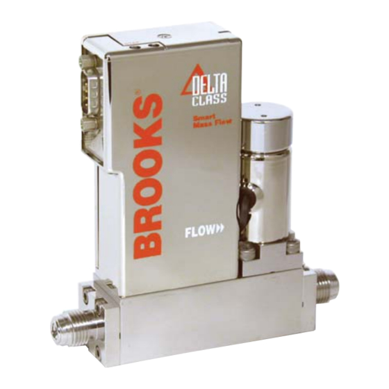
Models SLA7950 - SLA7960
Mass Flow Controllers & Meters
Model SLA7950S
Analog I/O
9-pin D-Connector
VCR Fittings
Model SLA7950D
Digital I/O
DeviceNet Downport
SLA7900 Series
Model SLA7950S
Analog I/O
15-pin D-Connector
VCR Fittings
Advertisement
Table of Contents
Troubleshooting

Related Manuals for Brooks SLA7950S


Summary of Contents for Brooks SLA7950S
- Page 1 Installation and Operation Manual X-TMF-SLA7900-MFC-eng Part Number: 541B022AAG SLA7900 Series August, 2009 ® Brooks Models SLA7950 - SLA7960 Mass Flow Controllers & Meters Model SLA7950S Model SLA7950S Analog I/O Analog I/O 9-pin D-Connector 15-pin D-Connector VCR Fittings VCR Fittings Model SLA7950D...
- Page 2 Essential Instructions Read this page before proceeding! Brooks Instrument designs, manufactures and tests its products to meet many national and international standards. Because these instruments are sophisticated technical products, you must properly install, use and maintain them to ensure they continue to operate within their normal specifications.
- Page 3 We appreciate this opportunity to service your flow measurement and control requirements with a Brooks Instrument device. Every day, flow customers all over the world turn to Brooks Instrument for solutions to their gas and liquid low-flow applications. Brooks provides an array of flow measurement and control products for various industries from biopharmaceuticals, oil and gas, fuel cell research and chemicals, to medical devices, analytical instrumentation, semiconductor manufacturing, and more.
- Page 4 Installation and Operation Manual X-TMF-SLA7900-MFC-eng Part Number: 541B022AAG SLA7900 Series August, 2009 THIS PAGE WAS INTENTIONALLY LEFT BLANK...
-
Page 5: Table Of Contents
Gas Conversion Factors ........................4-5 Orifice Sizing ............................ 4-7 Restrictor Sizing ..........................4-7 Section A CE Certification CE Certification of Mass Flow Equipment ..................A-1 Section B Zero Drift Diagnostic on SLA7950S ....................B-1 Warranty, Local Sales/Service Contact Information ............... Back Cover... - Page 6 Model SLA7950D MFC DeviceNet Digital I/O with Downport Connections(C-seal) ......1-9 Model SLA7950D MFC DeviceNet Digital I/O with VCR Fittings............1-9 Model SLA7950S MFC 15-pin D-Connector Analog with 1.5" Downport Connections (W-seal) ..1-10 15-pin D-Connector Shielded Cable Hookup Diagram Voltage I/O Version ........2-6 Common Electrical Hookups for 15-pin D-Connector Voltage I/O Version ........
-
Page 7: Section 1 Introduction
Broad Array of Communication Options Brooks offers traditional 0-5 volt and 4-20 mA analog options as well as RS-485 digital communications (“S-protocol”, based on HART). Brooks also offers control interface with... -
Page 8: Specifications
Zero drift can be accurately detected because Brooks MFCs have the ability to monitor both positive and negative flow signals. This diagnostic gives the user a higher level of confidence that the process has not shifted. - Page 9 Section 1 Introduction Installation and Operation Manual X-TMF-SLA7900-MFC-eng Part Number: 541B022AAG SLA7900 Series August, 2009 RATINGS: Pressure Equipment Directive (PED) 97/23/EC See Table 1 Table 1 PED Rating Mass Flow Flow Ranges Pressure PED Module H Controller N2 Equivalent Ratings Category Models Min.
- Page 10 Section 1 Introduction Installation and Operation Manual X-TMF-SLA7900-MFC-eng Part Number: 541B022AAG SLA7900 Series August, 2009 Outline Dimensions Refer to Figures 1-1 through 1-7Electrical Characteristics: Electrical Connections Analog I/O option: 9-pin D-connector or 15-pin D-Connector, male DeviceNet I/O option: 5-pin Micro-Connector, male RS-485 option: 15-pin D-Connector, male Analog I/O Pin Connections for 9-pin D-Connector: Function...
-
Page 11: General Wiring
Figure 1-1. This form of multi-drop capable communication provides access to many of the Brooks Digital Series functions for “control and monitor” operations, including: • Accurate setpoint adjustment and flow output measurement (including units of measure selection) •... - Page 12 The Brooks Digital Series is also available with DeviceNet communication capability. DeviceNet is an open digital protocol capable of high speeds and easy system connectivity. Brooks Instrument has several of its devices available on this popular networking standard, and is a member of ODVA (Open DeviceNet Vendors Association), the governing standard body for DeviceNet.
-
Page 13: Model Sla7950S Mfc Analog I/O 9-Pin D-Connector With Vcr Fittings
*MFM Outline drawing is identical to the MFC, except without the valve. Figure 1-2 Model SLA7950S MFC Analog I/O 9-pin D-Connector with VCR Fittings *MFM Outline drawing is identical to the MFC, except without the valve. Figure 1-3 Model SLA7950S MFC Analog I/O 9-pin D-Connector with Downport Connections (C-seal) -
Page 14: Model Sla7950S Mfc Analog I/O 15-Pin D-Connector With Vcr Fittings
*MFM Outline drawing is identical to the MFC, except without the valve. Figure 1-4 Model SLA7950S MFC Analog I/O 15-pin D-Connector with VCR Fittings *MFM Outline drawing is identical to the MFC, except without the valve. Figure 1-5 Model SLA7950S MFC Analog I/O 15-pin D-Connector with Downport Connections (C-seal) -
Page 15: Model Sla7950D Mfc Devicenet Digital I/O With Downport Connections(C-Seal)
Section 1 Introduction Installation and Operation Manual X-TMF-SLA7900-MFC-eng Part Number: 541B022AAG SLA7900 Series August, 2009 *MFM Outline drawing is identical to the MFC, except without the valve. Figure 1-6 Model SLA7950D MFC DeviceNet Digital I/O with Downport Connections (C-seal) *MFM Outline drawing is identical to the MFC, except without the valve. Figure 1-7 Model SLA7950D MFC DeviceNet Digital I/O with VCR Fittings... - Page 16 Section 1 Introduction Installation and Operation Manual X-TMF-SLA7900-MFC-eng Part Number: 541B022AAG SLA7900 Series August, 2009 *MFM Outline drawing is identical to the MFC, except without the valve. Figure 1-8 Model SLA7950S MFC 15-pin D-Connector Analog I/O with 1.5" Downport Connections (W-seal) 1-10...
-
Page 17: Section 2 Installation
Part Number: 541B022AAG SLA7900 Series August, 2009 2-1 General This section provides installation instructions for the Brooks SLA7900 Series. Figures 1-1 through Figure 1-7 show the SLA7900 series dimensions, gas connections and electrical connection locations for an MFC. 2-2 Receipt of Equipment When the instrument is received, the outside packing case should be checked for damage incurred during shipment. -
Page 18: Return Shipment
Part Number: 541B022AAG SLA7900 Series August, 2009 2-4 Return Shipment Prior to returning any instrument to the factory visit the Brooks website www.BrooksInstrument.com for a Return Materials Authorization Number (RMA#), or contact one of the following locations: Brooks Instrument 407 W. Vine Street P.O. -
Page 19: Gas Connections
Section 2 Installation Installation and Operation Manual X-TMF-SLA7900-MFC-eng Part Number: 541B022AAG SLA7900 Series August, 2009 2-7 Gas Connections Standard inlet and outlet connections supplied on the Model SLA7900 Series are 1/4"(M) VCR or Downport surface mount per Semi 2787 or Semi F82-0304. - Page 20 Section 2 Installation Installation and Operation Manual X-TMF-SLA7900-MFC-eng Part Number: 541B022AAG SLA7900 Series August, 2009 d. The SLA7900 Series device can be installed in any position. However,mounting in orientations other than the original factory calibration (see calibration data sheet supplied with the instrument) can result in a ±0.2% maximum full scale shift after rezeroing.
-
Page 21: Electrical Interface (Analog I/O)
MFC and MFM includes +13.5 - 27 Vdc, supply common, and a setpoint signal. The Brooks Digital electrical interface is designed to facilitate low-loss, quiet signal connections. Separate returns (commons) are supplied for the analog setpoint, analog flow signal, and the power supply. -
Page 22: Common Electrical Hookups For 15-Pin D-Connector Voltage I/O Version
RS-485, Common B (-) Input/Output GRN/WHT RS-485, Common A (+) Input/Output BLU/WHT * Brooks Read Out Models 0151, 0152, 0154, 0254 Figure 2-1 15-pin D-Connector Shielded Cable Hookup Diagram Figure 2-2 Common Electrical Hookups for 15-pin D-Connector Voltage I/O Version... -
Page 23: Recommended Wiring Configuration For Current Signals (Non-Isolated Power Supply)
Section 2 Installation Installation and Operation Manual X-TMF-SLA7900-MFC-eng Part Number: 541B022AAG SLA7900 Series August, 2009 Figure 2-3 Recommended Wiring Configuration for Current Signals (Non-Isolated Power Supply) Figure 2-4 Recommended Wiring Configuration for Current Signals (Isolated Power Supply) -
Page 24: Common Electrical Hookups For 9-Pin D-Connector Voltage I/O Version
Section 2 Installation Installation and Operation Manual X-TMF-SLA7900-MFC-eng Part Number: 541B022AAG SLA7900 Series August, 2009 Analog I/O Pin Connections for 9-pin D-Connector: Function 9-pin D-conn Valve Override, Input Flow Signal, 0-5 volt, Output (+) Power Supply, +13.5 Vdc to +27 Vdc (+) Power Supply, Common (-) Not Connected Setpoint, 0-5 Vdc, Input (+) -
Page 25: Operation Check Procedure (Analog I/O)
Section 2 Installation Installation and Operation Manual X-TMF-SLA7900-MFC-eng Part Number: 541B022AAG SLA7900 Series August, 2009 2-11 Operation Check Procedure (Analog I/O) a. Mount the MFC in its final orientation. b. Apply power to the MFC and allow approximately one hour for the instrument to warm up and stabilize its temperature. -
Page 26: Electrical Interface (Devicenet I/O)
Section 2 Installation Installation and Operation Manual X-TMF-SLA7900-MFC-eng Part Number: 541B022AAG SLA7900 Series August, 2009 2-12 Electrical Interface (DeviceNet I/O) Power and network signals are interfaced to the MFC through the standard 5-pin Micro-connector on the device. This connector is specified in the DeviceNet Specification, Vol. -
Page 27: Operation Check Procedure (Devicenet I/O)
(nitrogen) is 0.27, therefore the equivalent N needed is 100/0.27 = 370.4 sccm. This may require a pressure increase to make this flow rate. 2-14 DeviceNet Features Information regarding DeviceNet capability for the Brooks SLA7900 Series is available in the DeviceNet Supplemental Instruction manual. (X-DPT-DeviceNet-SLA7000-MFC-eng) 2-11... - Page 28 Section 2 Installation Installation and Operation Manual X-TMF-SLA7900-MFC-eng Part Number: 541B022AAG SLA7900 Series August, 2009 THIS PAGE WAS INTENTIONALLY LEFT BLANK 2-12...
-
Page 29: Section 3 Operation
Section 3 Operation Installation and Operation Manual X-TMF-SLA7900-MFC-eng Part Number: 541B022AAG SLA7900 Series August, 2009 3-1 General After the device has been properly installed in the process, it is ready for operation. When initiating flow, slowly open the valve to avoid a flow surge.A bypass is helpful in bringing the flow on smoothly. -
Page 30: Features
MFC, but with improved accuracy, step response and valve control. The analog interface matches that of Brooks' popular analog MFCs so the Model SLA7950 can be retrofitted into tools using analog MFCs. Other versions of the Model SLA7950 can provide a variety of digital protocols, for example DeviceNet. -
Page 31: Adaptive Valve Control
3-5 Analog Mode of Operation NOTE: Read Section 3-3, Features, before reading this section. A. Functional Description The analog interface is consistent with other Brooks analog MFCs. This includes a 0-5 volt setpoint input, 0-5 volt flow signal output and Valve Override input. -
Page 32: Externally Accessible Adjustment
Section 3 Operation Installation and Operation Manual X-TMF-SLA7900-MFC-eng Part Number: 541B022AAG SLA7900 Series August, 2009 F. Zeroing the MFC (Self-zero) It may be desirable to re-zero the flow sensor if it is operated at its temperature extremes or if it is positioned in an attitude other than that specified on the customer order. -
Page 33: Flow Control System Block Diagram
Section 3 Operation Installation and Operation Manual X-TMF-SLA7900-MFC-eng Part Number: 541B022AAG SLA7900 Series August, 2009 Figure 3-3 Flow Control System Block Diagram... - Page 34 Section 3 Operation Installation and Operation Manual X-TMF-SLA7900-MFC-eng Part Number: 541B022AAG SLA7900 Series August, 2009 THIS PAGE WAS INTENTIONALLY LEFT BLANK...
-
Page 35: Section 4 Maintenance & Troubleshooting
Section 4 Maintenance & Installation and Operation Manual X-TMF-SLA7900-MFC-eng Troubleshooting Part Number: 541B022AAG SLA7900 Series August, 2009 4-1 Overview No routine maintenance is required on the SLA7900 Series devices. If an in-line filter is used, the filtering elements should be periodically replaced. This section provides the following information: •... - Page 36 Section 4 Maintenance & Installation and Operation Manual X-TMF-SLA7900-MFC-eng Troubleshooting Part Number: 541B022AAG SLA7900 Series August, 2009 4-2 Troubleshooting Analog or DeviceNet Version This section contains suggestions to help diagnose MFC related problems in the gas distribution system and answers commonly asked questions. Failure of the flow rate or flow signal to achieve the setpoint.
- Page 37 Section 4 Maintenance & Installation and Operation Manual X-TMF-SLA7900-MFC-eng Troubleshooting Part Number: 541B022AAG SLA7900 Series August, 2009 Setpoint is below minimum. MFCs may have a settable low flow cutoff for the setpoint command. If setpoint is below this value, then MFC will not attempt to control.
- Page 38 Section 4 Maintenance & Installation and Operation Manual X-TMF-SLA7900-MFC-eng Troubleshooting Part Number: 541B022AAG SLA7900 Series August, 2009 DeviceNet Version What is the purpose of the LED’s on top of the SLA7900 Series MFC? There are two LED’s on top of a DevcieNet version MFC. The LED labeled ‘MOD’...
- Page 39 This scale shift can be approximated by using the ratio of the molar specific heat of the two gases or by sensor conversion factor. Consult factory or nearest Brooks Instrument rep for a list of sensor conversion factors. To change to a new gas, multiply the output reading by the ratio of the gas factor for the desired gas by the gas factor for the calibration gas used.
-
Page 40: Bench Troubleshooting Circuit
Section 4 Maintenance & Installation and Operation Manual X-TMF-SLA7900-MFC-eng Troubleshooting Part Number: 541B022AAG SLA7900 Series August, 2009 Example: The controller is calibrated for Nitrogen. The desired gas is Carbon Dioxide (CO The output reading is 75 sccm when Carbon Dioxide is flowing Then 75 x 0.74 = 55.5 sccm of (CO In order to calculate the conversion factor for a gas mixture, the following formula should be used:... -
Page 41: Orifice Sizing
Section 4 Maintenance & Installation and Operation Manual X-TMF-SLA7900-MFC-eng Troubleshooting Part Number: 541B022AAG SLA7900 Series August, 2009 4-4 Orifice Sizing The flow controller's orifice is factory-sized to a preselected gas, operating pressure and flow range. Note that the orifice is marked with its size in thousandths of an inch. - Page 42 Section 4 Maintenance & Installation and Operation Manual X-TMF-SLA7900-MFC-eng Troubleshooting Part Number: 541B022AAG SLA7900 Series August, 2009 Restrictors The SLA7900 Series MFC uses two types of restrictor assemblies depending on full scale flowrate and expected service conditions. Wire mesh for Nitrogen equivalent flow rates above 3.4 slpm. These restrictor assemblies are made from a cylinder of wire mesh and are easily cleaned if they become contaminated in service.
-
Page 43: Ce Certification Of Mass Flow Equipment
CE mærkning af Masse Flow udstyr Dato Januar-1996. Brooks Instrument har gennemført CE mærkning af elektronisk udstyr med succes, i henhold til regulativet om elektrisk støj (EMC direktivet 89/336/EEC). Der skal dog gøres opmærksom på benyttelsen af signalkabler i forbindelse med CE mærkede udstyr. - Page 44 Date January-1996. The Brooks (electric/electronic) equipment bearing the CE mark has been successfully tested to the regulations of the Electro Magnetic Compatibility (EMC directive 89/336/EEC). Special attention however is required when selecting the signal cable to be used with CE marked equipment.
- Page 45 Janvier 1996. Messieurs, Les équipements Brooks (électriques/électroniques) portant le label CE ont été testés avec succès selon les règles de la Compatibilité Electromagnétique (directive CEM 89/336/EEC). Cependant, la plus grande attention doit être apportée en ce qui concerne la sélection du câble utilisé pour véhiculer le signal d’un appareil portant le label CE.
- Page 46 E’ richiesta comunque una speciale attenzione nella scelta dei cavi di segnale da usarsi con la strumentazione soggetta a marchio Qualità dei cavi di segnale e dei relativi connettori: Brooks fornisce cavi di elevata qualità che soddisfano le specifiche richieste dalla certificazione CE. Se l’utente intende usare propri cavi, questi devono possedere una schermatura del 100%.
- Page 47 Januar 1996 Til den det angår Brooks Instrument elektrisk og elektronisk utstyr påført CE-merket har gjennomgått og bestått prøver som beskrevet i EMC forskrift om elektromagnetisk immunitet, direktiv 89/336/EEC. For å opprettholde denne klassifisering er det av stor viktighet at riktig kabel velges for tilkobling av det måletekniske utstyret.
- Page 48 Date : January 1996 Brooks (elektriska / elektronik) utrustning, som är CE-märkt, har testats och godkänts enligt gällande regler för elektromagnetisk kompabilitet (EMC direktiv 89/336/EEC). Speciell hänsyn måste emellertid tas vid val av signalkabel som ska användas tillsammans med CE-märkt utrustning.
-
Page 49: Section B
SLA7950S alarms to notify the user when an out of limits Installation Recommendations condition has been detected. Zero drift can be accurately... -
Page 50: Zdd Interlock Timing
The error limit can be set to any conditions. The SLA7950S uses a zero setpoint value value in the range 0.5% to 100% of full scale. to define a no-flow condition. However, since flow does... -
Page 51: B-3 Error Limits
Transition to safe state option is enabled and drift is detected, the MFC will transition to a “safe state” which for the SLA7950S means that the valve will be closed and 1. Flash the Alarm LED; red for alarm, green for the flow signal will be set to zero. -
Page 52: Connecting To The Sla7950S Service Port
232 serial port requires Brooks cable kit S778D023ZZZ. This kit includes a 3-wire cable and a RS-232 converter. The ZDDCT main panel is shown in Figure B-5. Some Follow the procedure below to connect the SLA7950S to helpful tips on using this application are: your PC. -
Page 53: About Zddct Window
The ZDDCT automatically detects all available COM ports and displays them in the Select Communications Port pull-down box. Select the COM port that the SLA7950S MFC to be configured is connected to. The ZDDCT supports USB to RS-232... - Page 54 Part Number: 541B022AHG SLA7900 Series August, 2009 Step 2 – Select the type of Brooks MFC to be configured by using the Select product pull-down. The ZDDCT will attempt to communicate with the connected device, verify that the device has the ZDD feature enabled, and will then read and display the ZDD configuration parameters.
- Page 55 Installation and Operation Manual Section B X-TMF-SLA7900-MFC-eng Zero Drift Diagnostic on SLA7950S Part Number: 541B022AHG SLA7900 Series August, 2009 Contact Enable - If selected, a warning/alarm condition will cause the open-collector output at pin 3 of the device’s 15 pin D-connector to be active (closed).
- Page 56 SLA7900 Series August, 2009 Step 4 – Press the Send button to send the configuration to the device. The parameters in the SLA7950S will be updated with the values as configured during step 3. When the parameters have all been successfully written and verified, the following dialog box will appear.
- Page 57 Installation and Operation Manual X-TMF-SLA7900-MFC-eng Part Number: 541B022AAG SLA7900 Series August, 2009 THIS PAGE WAS INTENTIONALLY LEFT BLANK...
- Page 58 BROOKS SERVICE AND SUPPORT Brooks is committed to assuring all of our customers receive the ideal flow solution for their application, along with outstanding service and support to back it up. We operate first class repair facilities located around the world to provide rapid response and support.
Need help?
Do you have a question about the SLA7950S and is the answer not in the manual?
Questions and answers