
Related Manuals for Brooks 5850i


Summary of Contents for Brooks 5850i
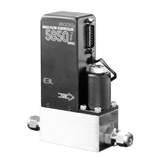
- Page 1 Installation and Operation Manual X-TMF-5850i-MFC-eng Part Number: 541B108AAG ® Brooks Model 5850i November, 2008 Model 5850i Mass Flow Controller...
- Page 2 Essential Instructions Read this page before proceeding! Brooks Instrument designs, manufactures and tests its products to meet many national and international standards. Because these instruments are sophisticated technical products, you must properly install, use and maintain them to ensure they continue to operate within their normal specifications.
- Page 3 We appreciate this opportunity to service your flow measurement and control requirements with a Brooks Instrument device. Every day, flow customers all over the world turn to Brooks Instrument for solutions to their gas and liquid low-flow applications. Brooks provides an array of flow measurement and control products for various industries from biopharmaceuticals, oil and gas, fuel cell research and chemicals, to medical devices, analytical instrumentation, semiconductor manufacturing, and more.
- Page 4 Installation and Operation Manual X-TMF-5850i-MFC-eng Part Number: 541B108AAG ® Brooks Model 5850i November, 2008 THIS PAGE WAS INTENTIONALLY LEFT BLANK...
-
Page 5: Table Of Contents
Contents Installation and Operation Manual X -TMF-5850i-MFC-eng Part Number: 541B108AAG Brooks ® Model 5850i November, 2008 Section 1 Introduction Paragraph Page Number Number Purpose ................1-1 Description ................ 1-1 Specifications ..............1-3 Section 2 Installation Receipt of Equipment ............2-1 Recommended Storage Practice ........ - Page 6 Sensor Troubleshooting ............ 4-4 Conversion Factors (Nitrogen Base) ........ 4-12 Model 5850i Orifice Sizing Nomograph ......4-16 Model 5850i Standard Restrictors ........4-19 Model 5850i Replacement Parts List ......... 5-2 Tool and Spare Part Kits for 5850i Series ......5-3...
-
Page 7: Introduction
This instruction manual is intended to provide the user with all the information necessary to install, operate and maintain the Brooks 5850i Mass Flow Controller. This manual is organized into five sections: Section 1... -
Page 8: Command Steps, Soft Start Disabled
Section 1 Introduction Installation and Operation Manual X-TMF-5850i-MFC-eng Part Number: 541B108AAG Brooks ® Model 5850i November, 2008 Figure 1-1 Command Steps, Soft Start Disabled Figure 1-2 0 - 100% Command Step, Soft Start Enabled... -
Page 9: Specifications
Section 1 Introduction Installation and Operation Manual X-TMF-5850i-MFC-eng Part Number: 541B108AAG Brooks ® Model 5850i November, 2008 1-3 Specifications Standard Ranges 3 sccm to slpm* (nitrogen equivalent) Accuracy ±1% full scale including linearity at calibrated conditions ±1.5% full scale including linearity for flow ranges greater than 20 slpm. - Page 10 Section 1 Introduction Installation and Operation Manual X-TMF-5850i-MFC-eng Part Number: 541B108AAG Brooks ® Model 5850i November, 2008 Temperature Sensitivity Zero: Less than ±0.075% full scale per degree C. Span: Less than ±1.0% full scale shift over 10-50°C range. Mounting Attitude Sensitivity ±0.5% maximum full scale deviation after re-zeroing.
-
Page 11: Receipt Of Equipment
E-mail: BrooksEu@BrooksInstrument.com 2-2 Recommended Storage Practice If intermediate or long-term storage is required for equipment as supplied by Brooks Instrument, it is recommended that said equipment be stored in accordance with the following: a. Within the original shipping container. b. Store in a sheltered area with the following conditions: 1. -
Page 12: Return Shipment
Model 5850i November, 2008 2-3 Return Shipment Prior to returning any Brooks equipment to the factory, contact the factory - for a Return Materials Authorization Number (RMA#). This can be obtained at Brooks Instrument, Product Service Department, 407 West Vine Street, Hatfield, PA 19440-0903, or call toll free 1-888-554-FLOW (3569). -
Page 13: Installation
Figure 2-1 Model 5850i Dimensions 2-5 Installation (Refer to Figures 2-1 through 2-4) Recommended installation procedures: a. The Model 5850i should be located in a clean dry atmosphere relatively free from shock and vibration. b. Leave sufficient room for access to the electrical components. -
Page 14: In-Line Filter
Figure 2-2 "D" Type Connector Pin Arrangement Note: The control valve in the Model 5850i provides precision control and is not designed for positive shut-off. If positive shut-off is required, it is recommended that a separate shut-off valve be installed in-line. -
Page 15: Electrical Interfacing
Electrical Hook-up Setpoint (Command) Input The 5850i Mass Flow Controller can be used with a current (4-20 mAdc) or voltage (0-5 Vdc) setpoint. To use the current setpoint, connect the setpoint (+) signal to pin 7 and the setpoint return (-) signal to pin 1 of the D-connector and configure the PC Board per Section 2-7. -
Page 16: Common Electrical Hook-Ups
Installation and Operation Manual X-TMF-5850i-MFC-eng Part Number: 541B108AAG Brooks ® Model 5850i November, 2008 Figure 2-4 Common Electrical Hook-Ups Supply The power for the mass flow controller is connected to pin 5 (+22.5 to +28 Vdc) and pin 9 (supply common) of the D-connector. Refer to Section 1-3 for the power requirements. -
Page 17: Configuring The Pc Board
Installation and Operation Manual X-TMF-5850i-MFC-eng Part Number: 541B108AAG Brooks ® Model 5850i November, 2008 Valve Override (connection optional) The valve override function allows full opening and closing of the valve independent of the setpoint: To open the valve, apply +15 to +28 Vdc to pin 12 To close the valve, connect pin 12 to ground. - Page 18 Section 2 Installation Installation and Operation Manual X-TMF-5850i-MFC-eng Part Number: 541B108AAG Brooks ® Model 5850i November, 2008 THIS PAGE WAS INTENTIONALLY LEFT BLANK...
-
Page 19: Theory Of Operation
The span adjustment in the electronics affects the fine adjustment of the controller's full scale flow. In addition to the mass flow sensor, the Model 5850i Mass Flow Controller has an integral control valve and control circuit, as shown in Figure 3-2. -
Page 20: Operating Procedure
X-TMF-5850i-MFC-eng Part Number: 541B108AAG ® Brooks Model 5850i November, 2008 Figure 3-1 Flow Sensor Operational Diagram Soft Start enabled by moving a jumper on the PC Board. This circuit provides a slow injection of the gas as a protection to the process, particularly those using a volatile or reactive gas. -
Page 21: Zero Adjustment
Figure 3-2 Flow Control System Block Diagram 3-3 Zero Adjustment Each 5850i is factory adjusted to provide a zero ±10 mVdc signal or a 4 mAdc ±0.05 mAdc signal at zero flow. The adjustment is made in our calibration laboratory which is temperature controlled to 21.1°C (70°F ±2°F). -
Page 22: Calibration Procedure
NOTE 2: Calibration of the 5850i mass flow controller requires the use of a digital voltmeter (DVM) and a precision flow standard calibrator such as the Brooks Vol-U-Meter. It is recommended that the calibration be performed only by trained and qualified service personnel. - Page 23 X-TMF-5850i-MFC-eng Part Number: 541B108AAG ® Brooks Model 5850i November, 2008 f. Connect the DVM positive lead to TP1 (100x sensor voltage) and the negative lead to TP4 (circuit common). The setpoint should still be set at 100% flow (5.000V). Measure the flow rate using suitable volumetric calibration equipment.
-
Page 24: Model 5850I Calibration Connections
Section 3 Operation Installation and Operation Manual X-TMF-5850i-MFC-eng Part Number: 541B108AAG ® Brooks Model 5850i November, 2008 Figure 3-3 Model 5850i Calibration Connections Figure 3-4 Adjustment Potentiometer Location... -
Page 25: Pc Board Jumper Location & Function
Section 3 Operation Installation and Operation Manual X-TMF-5850i-MFC-eng Part Number: 541B108AAG ® Brooks Model 5850i November, 2008 Figure 3-5 PC Board Jumper Location & Function... -
Page 26: Response
Refer to Section 4-7. 3-5 Response Fast Response Adjustment Two methods of adjusting the step response of the 5850i mass flow controllers can be used. Method Number 1 describes a procedure that will get the step response close to optimum quickly and without any flow measuring equipment. - Page 27 (500 millisecond response to be within 0.2% of final value or better) in series with the 5850i and a storage oscilloscope or recorder. a. Allow the flow controller to stabilize at 0% setpoint for at least thirty seconds.
- Page 28 Section 3 Operation Installation and Operation Manual X-TMF-5850i-MFC-eng Part Number: 541B108AAG ® Brooks Model 5850i November, 2008 THIS PAGE WAS INTENTIONALLY LEFT BLANK 3-10...
-
Page 29: Bench Troubleshooting
Brooks Model 5850i November, 2008 4-1 General No routine maintenance is required on the Model 5850i other than an occasional cleaning. If an in-line filter is used, the filtering element should periodically be replaced or ultrasonically cleaned. 4-2 Troubleshooting A. System Checks The 5850i is generally used as a component in gas handling systems which can be quite complex. - Page 30 Section 4 Maintenance Installation and Operation Manual X-TMF-5850i-MFC-eng Part Number: 541B108AAG ® Brooks Model 5850i November, 2008 Table 4-1 Bench Troubleshooting Trouble Possible Cause Check/Corrective Action Actual flow overshoots setpoint by Anticipate potentiometer out of adjustment. Adjust anticipate potentiometer. Refer to Section 3-5 .
-
Page 31: Torque Sequence For The Valve Retainer Plate
NOTE: Do not attempt to disassemble the sensor. Cleaning Procedures Should the Model 5850i Mass Flow Controller require cleaning due to deposition, use the following procedures: 1. Remove the unit from the system. 2. Refer to Section 4-4 to disassemble the controller. - Page 32 X-TMF-5850i-MFC-eng Part Number: 541B108AAG ® Brooks Model 5850i November, 2008 Table 4-2 Sensor Troubleshooting 4. Inspect the orifice for clogging by holding it in front of a light source and looking for light through the bore. Clean by soaking in a suitable non-residuous solvent and directing a stream of compressed dry nitrogen through the bore.
- Page 33 Section 4 Maintenance Installation and Operation Manual X-TMF-5850i-MFC-eng Part Number: 541B108AAG ® Brooks Model 5850i November, 2008 Figure 4-2a Valve Adjusting Spacer Locations (Normally Closed Valve N.C.)
- Page 34 Section 4 Maintenance Installation and Operation Manual X-TMF-5850i-MFC-eng Part Number: 541B108AAG ® Brooks Model 5850i November, 2008 Figure 4-2b Valve Adjusting Spacer Locations (Normally Open Valve N.O.)
- Page 35 Refer to Section 3-4. 4-4 Disassembly and Assembly The Model 5850i Mass Flow Controller may be disassembled in the field by the user for cleaning, re-ranging or servicing. Disassemble and assemble the controller as follows: (for normally open valves N.O.) Figure 3-5 shows the location and function of jumpers.
-
Page 36: Voltmeter Connections For Valve Adjustment
X-TMF-5850i-MFC-eng Part Number: 541B108AAG ® Brooks Model 5850i November, 2008 Figure 4-3 Voltmeter Connections for Valve Adjustment 6. Remove and note the position of the valve spring spacers (10), which may be located above and/or below the lower guide spring (8). Remove the preload spacer spring (33)(NO Valve). - Page 37 Note: Do not attempt to disassemble the sensor assembly. 12.Remove the sensor assembly O-rings (17) from the flow controller body (14). Using the Brooks O-ring removal tool will help prevent scratching the sealing surface. 13.Remove the adapter fittings (27) from the flow controller body (14).
- Page 38 12.Prior to installation leak and pressure test to any applicable pressure vessel codes. C. Adjusting the Control Valve The 5850i control valve has been factory adjusted to insure proper operation. Readjustment is only required if any of the following parts have been replaced:...
- Page 39 Part Number: 541B108AAG ® Brooks Model 5850i November, 2008 and the total travel of the valve. If the air gap is too small, the plunger travel may be insufficient to fully open the valve. Also, the magnetic force may be too high for a given valve coil voltage.
- Page 40 X-TMF-5850i-MFC-eng Part Number: 541B108AAG ® Brooks Model 5850i November, 2008 4-5 Use of the Conversion Tables If a mass flow controller is operated on a gas other than the gas it was calibrated with, a scale shift will occur in the relation between the output signal and the mass flow rate.
-
Page 41: Conversion Factors (Nitrogen Base)
Section 4 Maintenance Installation and Operation Manual X-TMF-5850i-MFC-eng Part Number: 541B108AAG ® Brooks Model 5850i November, 2008 Table 4-3 Conversion Factors (Nitrogen Base) GAS NAME FORMULA SENSOR ORIFICE DENSITY FACTOR FACTOR (kg/m Acetylene 0.615 0.970 1.173 Mixture 0.998 1.018 1.293 Allene 0.478... - Page 42 Section 4 Maintenance Installation and Operation Manual X-TMF-5850i-MFC-eng Part Number: 541B108AAG ® Brooks Model 5850i November, 2008 Table 4-3 Conversion Factors (Nitrogen Base) Continued. GAS NAME FORMULA SENSOR ORIFICE DENSITY FACTOR FACTOR (kg/m Hydrogen 1.008 0.269 0.090 Hydrogen Bromide 0.987 1.695...
- Page 43 November, 2008 4-6 Use of Orifice Sizing Nomograph The Orifice and Restrictor Sizes for 5850i should be sized using the "Brooks Thermal Mass Flowmeter Sizing Selection Program" Revision 8.6 or later. A copy can be requested through your local Brooks Sales Representive or through the Brooks Customer Service Department.
- Page 44 X-TMF-5850i-MFC-eng Part Number: 541B108AAG ® Brooks Model 5850i November, 2008 Example: What is the air equivalent flow rate of 2000 sccm Hydrogen? In order to calculate the orifice conversion factor when using a gas mixture, the following formula must be used:...
-
Page 45: Model 5850I Orifice Sizing Nomograph
Section 4 Maintenance Installation and Operation Manual X-TMF-5850i-MFC-eng Part Number: 541B108AAG ® Brooks Model 5850i November, 2008 Table 4-4 Model 5850i Orifice Sizing Nomograph 4-17... -
Page 46: Example Nomograph
Installation and Operation Manual X-TMF-5850i-MFC-eng Part Number: 541B108AAG ® Brooks Model 5850i November, 2008 Figure 4-4 Example Nomograph If these conditions do not exist, pressure drop equals the inlet pressure minus the outlet pressure. Then Δp = 64.7 - 44.7 = 20 psi Using the nomograph, locate the pressure drop (psi) on the vertical line marked "Δp"... - Page 47 X-TMF-5850i-MFC-eng Part Number: 541B108AAG ® Brooks Model 5850i November, 2008 conditions. If this point is between two orifice sizes, select the next largest size orifice to ensure adequate flow. If the orifice selected falls below .0013, choose .0013 size orifice.
-
Page 48: Model 5850I Standard Restrictors
Part Number: 541B108AAG ® Brooks Model 5850i November, 2008 Table 4-5 Model 5850i Standard Restrictors Example: The desired gas is Silane (SiH4). The desired full scale flow rate is 200 sccm Sensor conversion factor is 0.68 from Table 4-3. Air equivalent flow = 200/0.68 = 294.1 sccm air. - Page 49 Installation and Operation Manual X-TMF-5850i-MFC-eng Part Number: 541B108AAG ® Brooks Model 5850i November, 2008 Sensor conversion factor for the mixture is: Air equivalent flow = 20/.903 = 22.15 slpm air. In this example, a size 4 wire mesh assembly would be selected.
- Page 50 Section 4 Maintenance Installation and Operation Manual X-TMF-5850i-MFC-eng Part Number: 541B108AAG ® Brooks Model 5850i November, 2008 THIS PAGE WAS INTENTIONALLY LEFT BLANK 4-22...
-
Page 51: Model 5850I Parts Drawing
Part Number: 541B108AAG ® Brooks Model 5850i November, 2008 5-1 General When ordering parts, please specify: Brooks Serial Number Model Number Part Description Part Number Quantity (Refer to Figure 5-1 and Tables 5-1 and 5-2). Figure 5-1 Model 5850i Parts Drawing... - Page 52 Section 5 Parts List Installation and Operation Manual X-TMF-5850i-MFC-eng Part Number: 541B108AAG ® Brooks Model 5850i November, 2008 Table 5-1 Model 5850i Replacement Parts List Item Qty. Description Part Number Jam Nut 573B027ACK Coil Assembly S185Z271AAA Screw, Valve 751C322AWA Retaining Plate...
-
Page 53: Model 5850I Replacement Parts List
Section 5 Parts List Installation and Operation Manual X-TMF-5850i-MFC-eng Part Number: 541B108AAG ® Brooks Model 5850i November, 2008 Table 5-1 Model 5850i Replacement Parts List (continued) Item Quantity Description Part Number Fitting, 1/4" Compression, Swagelok 320B136BMA Fitting, 1/4" Male VCR, Cajon 315Z036BMA Fitting, 1/4"... - Page 54 Section 5 Parts List Installation and Operation Manual X-TMF-5850i-MFC-eng Part Number: 541B108AAG ® Brooks Model 5850i November, 2008 THIS PAGE WAS INTENTIONALLY LEFT BLANK...
- Page 55 CE mærkning af Masse Flow udstyr Dato Januar-1996. Brooks Instrument har gennemført CE mærkning af elektronisk udstyr med succes, i henhold til regulativet om elektrisk støj (EMC direktivet 89/336/EEC). Der skal dog gøres opmærksom på benyttelsen af signalkabler i forbindelse med CE mærkede udstyr.
- Page 56 Date January-1996. The Brooks (electric/electronic) equipment bearing the CE mark has been successfully tested to the regulations of the Electro Magnetic Compatibility (EMC directive 89/336/EEC). Special attention however is required when selecting the signal cable to be used with CE marked equipment.
- Page 57 Janvier 1996. Messieurs, Les équipements Brooks (électriques/électroniques) portant le label CE ont été testés avec succès selon les règles de la Compatibilité Electromagnétique (directive CEM 89/336/EEC). Cependant, la plus grande attention doit être apportée en ce qui concerne la sélection du câble utilisé pour véhiculer le signal d’un appareil portant le label CE.
- Page 58 E’ richiesta comunque una speciale attenzione nella scelta dei cavi di segnale da usarsi con la strumentazione soggetta a marchio Qualità dei cavi di segnale e dei relativi connettori: Brooks fornisce cavi di elevata qualità che soddisfano le specifiche richieste dalla certificazione CE. Se l’utente intende usare propri cavi, questi devono possedere una schermatura del 100%.
- Page 59 Data Janeiro de 1996. O equipamento (eléctrico/electrónico) Brooks com a marca CE foi testado com êxito nos termos do regulamento da Compatibilidade Electromagnética (directiva CEM 89/336/EEC). Todavia, ao seleccionar-se o cabo de sinal a utilizar com equipamento contendo a marca CE, será necessário ter uma atenção especial.
- Page 60 Date : January 1996 Brooks (elektriska / elektronik) utrustning, som är CE-märkt, har testats och godkänts enligt gällande regler för elektromagnetisk kompabilitet (EMC direktiv 89/336/EEC). Speciell hänsyn måste emellertid tas vid val av signalkabel som ska användas tillsammans med CE-märkt utrustning.
- Page 61 Installation and Operation Manual X-TMF-5850i-MFC-eng Part Number: 541B108AAG ® Brooks Model 5850i November, 2008 THIS PAGE WAS INTENTIONALLY LEFT BLANK...
- Page 62 BROOKS SERVICE AND SUPPORT Brooks is committed to assuring all of our customers receive the ideal flow solution for their application, along with outstanding service and support to back it up. We operate first class repair facilities located around the world to provide rapid response and support.
Need help?
Do you have a question about the 5850i and is the answer not in the manual?
Questions and answers