Table of Contents
Advertisement
Quick Links
Installation and Operation Manual
X -TMF-5965-5851EM-MFC-eng
Part Number: 541B122AAG
September, 2009
®
Brooks
Models 5965, 5851EM
Mass Flow Controllers
Model 5965
Mass Flow Controller
with Card Edge
Brooks
Model 5851EM
Mass Flow Controller
with D-Connector
®
Models 5965, 5851EM
Model 5851EM Downported
Mass Flow Controller
with Card Edge
Advertisement
Table of Contents

Related Manuals for Brooks 5851EM Series


Summary of Contents for Brooks 5851EM Series
- Page 1 Installation and Operation Manual X -TMF-5965-5851EM-MFC-eng Part Number: 541B122AAG ® Brooks Models 5965, 5851EM September, 2009 ® Brooks Models 5965, 5851EM Mass Flow Controllers Model 5851EM Downported Model 5965 Mass Flow Controller Mass Flow Controller with Card Edge with Card Edge...
- Page 2 Essential Instructions Read this page before proceeding! Brooks Instrument designs, manufactures and tests its products to meet many national and international standards. Because these instruments are sophisticated technical products, you must properly install, use and maintain them to ensure they continue to operate within their normal specifications.
- Page 3 We appreciate this opportunity to service your flow measurement and control requirements with a Brooks Instrument device. Every day, flow customers all over the world turn to Brooks Instrument for solutions to their gas and liquid low-flow applications. Brooks provides an array of flow measurement and control products for various industries from biopharmaceuticals, oil and gas, fuel cell research and chemicals, to medical devices, analytical instrumentation, semiconductor manufacturing, and more.
- Page 4 Installation and Operation Manual X -TMF-5965-5851EM-MFC-eng Part Number:541B122AAG Brooks ® Models 5965, 5851EM September, 2009 THIS PAGE WAS INTENTIONALLY LEFT BLANK...
-
Page 5: Table Of Contents
Installation and Operation Manual Contents X -TMF-5965-5851EM-MFC-eng Part Number: 541B122AAG Brooks ® Models 5965, 5851EM September, 2009 Paragraph Page Number Number Section 1 Introduction How to Use This Manual ......................1-1 Description ..........................1-1 Specifications ..........................1-3 Section 2 Installation General ............................ - Page 6 Installation and Operation Manual Contents X -TMF-5965-5851EM-MFC-eng Part Number:541B122AAG Brooks ® Models 5965, 5851EM September, 2009 Figures Figure Page Number Number 0 to 100% Command Step, Soft Start Enabled ............... 1-2 MFC/MFM Dimensional Drawing for Models 5965, 5851EM with D-Connector orCard Edge with VCR Fittings ......................
-
Page 7: Section 1 Introduction
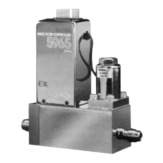
Warranty, Local Sales/Service Contact Information 1-2 Description The Brooks Model 5965 and 5851EM Mass Flow Controllers are used in gas flow handling systems where very low leakage and high performance are required. Models 5965 and 5851EM incorporate metal seals or welded joints, insuring leak integrity for high purity and high vacuum applications. -
Page 8: To 100% Command Step, Soft Start Enabled
Installation and Operation Manual Section 1 Introduction X-TMF-5965-5851EM-MFC-eng Part Number: 541B122AAG ® Brooks Models 5965, 5851EM September, 2009 • Fast response control permits rapid gas settling times with minimal over/undershoot. • Soft start provides a flow ramping function which slows down the introduction of process gas for those processes which cannot tolerate rapid flow transition. -
Page 9: Specifications
Installation and Operation Manual Section 1 Introduction X-TMF-5965-5851EM-MFC-eng Part Number: 541B122AAG ® Brooks Models 5965, 5851EM September, 2009 • Remote transducer input (Note 1) is accessed via terminal 5 on the Card Edge or Pin 15 on the D-Connector version. This feature allows the use of the integral control electronics and valve to regulate flow in response to the signal from an external 0-5 Vdc signal. - Page 10 Electrical Connections Card Edge: 30 micorinch gold over low stress nickel-plated copper D-Connector: DA-15P Electrical Pinouts Card Edge: Compatible with Brooks Model 5965/5851EM as well as most competitve models D-Connector: Compatible with Brooks Models 5850C, D and E. Environmental Conditions Installation category: "I"...
- Page 11 Installation and Operation Manual Section 1 Introduction X-TMF-5965-5851EM-MFC-eng Part Number: 541B122AAG ® Brooks Models 5965, 5851EM September, 2009 ELECTRICAL CHARACTERISTICS (continued): Differential Pressure Voltage I/O option Valve orifice sized for any pressure drop between 5 to 50 psi (Minimum pressure drop depends on gas and range). Refer to Orifice Sizing, Section 4-5.
-
Page 12: Mfc/Mfm Dimensional Drawing For Models 5965, 5851Em With D-Connector Or
Installation and Operation Manual Section 1 Introduction X-TMF-5965-5851EM-MFC-eng Part Number: 541B122AAG ® Brooks Models 5965, 5851EM September, 2009 Figure 1-2 MFC/MFM Dimensional Drawing for Models 5965, 5851EM with D-Connector or Card Edge with VCR Fittings... -
Page 13: Mfc/Mfm Dimensional Drawing For Models 5965, 5851Em With D-Connector Or Card Edgedownported
Installation and Operation Manual Section 1 Introduction X-TMF-5965-5851EM-MFC-eng Part Number: 541B122AAG ® Brooks Models 5965, 5851EM September, 2009 Figure 1-3 MFC/MFM Dimensional Drawing for Models 5965, 5851EM with D-Connector or Card Edge, Downported... - Page 14 Installation and Operation Manual Section 1 Introduction X-TMF-5965-5851EM-MFC-eng Part Number: 541B122AAG ® Brooks Models 5965, 5851EM September, 2009 THIS PAGE WAS INTENTIONALLY LEFT BLANK...
-
Page 15: Section 2 Installation
Pass your Model 5965/5851EM into your clean area. Note: Remove the second clean room compatible bag only when the equipment is ready to be tested and/or installed in your clean system. Brooks Instrument 407 W. Vine Street P.O. Box 903... -
Page 16: Recommended Storage Practice
Relative humidity 45% nominal, 60% maximum, 25% minimum. 2-4 Return Shipment Prior to returning any instrument to the factory, contact your nearest Brooks location for a Return Materials Authorization Number (RMA#). This can be obtained from one of the following locations: Brooks Instrument 407 W. -
Page 17: Transit Precaution
Installation and Operation Manual Section 2 Installation X-TMF-5965-5851EM-MFC-eng Part Number: 541B122AAG ® Brooks Models 5965, 5851EM September, 2009 2-5 Transit Precautions To safeguard the instrument against transportation damage, it is recommended to keep the instrument in its factory container until ready for installation. -
Page 18: In-Line Filter
Installation and Operation Manual Section 2 Installation X-TMF-5965-5851EM-MFC-eng Part Number: 541B122AAG ® Brooks Models 5965, 5851EM September, 2009 2-8 In-Line Filter It is recommended that an in-line filter be installed upstream from the controller to prevent the possibility of any foreign material entering the flow sensor or control valve. - Page 19 Installation and Operation Manual Section 2 Installation X-TMF-5965-5851EM-MFC-eng Part Number: 541B122AAG ® Brooks Models 5965, 5851EM September, 2009 CAUTION Use caution when installing surface mount (downported) controllers. Most metal seals reused after compression. Follow the seal manufacturers’ recommendations for installation. Tighten the mounting screws in 10 in-lb.
-
Page 20: Electrical Interface
Installation and Operation Manual Section 2 Installation X-TMF-5965-5851EM-MFC-eng Part Number: 541B122AAG ® Brooks Models 5965, 5851EM September, 2009 Note:The control valve in the Models 5965 and 5851EM provides precision control and is not designed for positive shut-off. lf positive shut-off is required, it is recommended that a separate shut-off valve be installed in- line. -
Page 21: D-Connector Pin Arrangement (Voltage I/O Version)
Installation and Operation Manual Section 2 Installation X-TMF-5965-5851EM-MFC-eng Part Number: 541B122AAG ® Brooks Models 5965, 5851EM September, 2009 Pin No. Function Color Code Command Common (Command Pot "CCW") Black 0-5 Volt Signal Output White External Valve Return (See Note 3)**... - Page 22 Pin 10 is f requently grounded. ln these situations the 5 Volt reference output must be disabled. Refer to Section 2-7. For installations which will be connected to Brooks secondary electronics, the Card Edge version must have the 5 Volt reference enabled on pin 10.
-
Page 23: Common Electrical Hookups Current I/O Version
Installation and Operation Manual Section 2 Installation X-TMF-5965-5851EM-MFC-eng Part Number: 541B122AAG ® Brooks Models 5965, 5851EM September, 2009 Grounding the valve test point pin willcause the valve to open fully regardless of command input voltage. Note: For normally open valves grounding this pin will cause the valve to fully close. -
Page 24: Configuring The Pc Board
Installation and Operation Manual Section 2 Installation X-TMF-5965-5851EM-MFC-eng Part Number: 541B122AAG ® Brooks Models 5965, 5851EM September, 2009 Electrical Hookup (Current I/O Option) Setpoint (Command) lnput The Model 5965/5851EM Mass Flow Controller can be used with a current (4-20 mAdc) or voltage (0-5 Vdc) setpoint. To use the current setpoint, connect the setpoint (+) signalto Pin 7 and the setpoint return (-) signal to Pin 1 of the D-Connector and configure the PC board per Section 2-10.To... - Page 25 Refer to Figures 2-1 and 3-3.Terminal 10 can be jumper selected as 5 Volt reference output, external valve return or “not used”. The 5 Volt reference output is required by Brooks secondary electronics, or if a potentiometer is to be used to generate the command signal.To enable the 5 Volt reference output on Terminal 10 place the yellow jumper at J1 in the D-E position.
- Page 26 Installation and Operation Manual Section 2 Installation X-TMF-5965-5851EM-MFC-eng Part Number: 541B122AAG ® Brooks Models 5965, 5851EM September, 2009 RemoteTransducer lnput (Factory lnstalled Option) Refer to Figures 3-3, 3-4 and 3-5. To allow the Model 5965/5851EM control circuitry and valve to be used with an 0-5 Vdc external transducer signal, a green jumper is moved to the lower two pins at J7.
-
Page 27: Section 3 Operation
Installation and Operation Manual Section 3 Operation X-TMF-5965-5851EM-MFC-eng Part Number: 541B122AAG ® Brooks Models 5965, 5851EM September, 2009 3-1 Theory of Operation The thermal mass flow sensing technique used in the Model 5851EM works as follows: Constant power (p) is provided to the heater winding which is located at the midpoint of the sensor tube. -
Page 28: Operating Procedure
Installation and Operation Manual Section 3 Operation X-TMF-5965-5851EM-MFC-eng Part Number: 541B122AAG ® Brooks Models 5965, 5851EM September, 2009 The flow restrictor shown in Figure 3-1 peforms a ranging function similar to a shunt resistor in an electrical ammeter. The restrictor provides a pressure drop that is linear with flow rate. -
Page 29: Zero Adjustment
Figure 3-6) until the desired output signal is obtained. 3-4 Calibration Procedure Note 1: lf the valve has been disassembled and any of the following parts have been replaced, the device must be returned to Brooks Instrument for control valve adjustment before the Model 5965/5851EM may be calibrated. -
Page 30: Card Edge Pc Board Jumper Location And Function
Models 5965, 5851EM September, 2009 Note 4: lf Brooks secondary electronics are being used as a power supply during the calibration, the 5 volt reference must be enabled on the card Edge version for proper operation (see Section 2-7). Remember to deactivate the 5 Volt reference before installing the calibrated mass flow controller in the system where Terminal 10 is grounded. -
Page 31: D-Connector Pc Board Jumper Location And Function (Voltage I/O Version)
Installation and Operation Manual Section 3 Operation X-TMF-5965-5851EM-MFC-eng Part Number: 541B122AAG ® Brooks Models 5965, 5851EM September, 2009 Figure 3-4 D-Connector PC Board Jumper Location and Function (Voltage I/O Version) -
Page 32: D-Connector Pc Board Jumper Location And Function (Current I/O Version)
Installation and Operation Manual Section 3 Operation X-TMF-5965-5851EM-MFC-eng Part Number: 541B122AAG ® Brooks Models 5965, 5851EM September, 2009 J7 - GREEN SETPOINT INPUT SIGNAL TYPE (Mass Flow Controller only) 4 - 20 mA 0 - 5 VOLTS NOTE: The 5V Reference is always enabled and is available on Pin 11. - Page 33 Installation and Operation Manual Section 3 Operation X-TMF-5965-5851EM-MFC-eng Part Number: 541B122AAG ® Brooks Models 5965, 5851EM September, 2009 Figure 3-6 Model 5851EM Calibration Connections Note 5: when calibrating the current l/o Version, it is easiest to calibrate using 0-5 vdc command and flow signals. Refer to section 2, Figures 2-4, 2-6 and 3-5 for proper hookups.
-
Page 34: Fast Response Adjustment
Installation and Operation Manual Section 3 Operation X-TMF-5965-5851EM-MFC-eng Part Number: 541B122AAG ® Brooks Models 5965, 5851EM September, 2009 b. Adjust the anticipate potentiometer with 20 clockwise full turns. Next, adjust the anticipate potentiometer with 10 counterclockwise turns to center the potentiometer. This will provide a rough adjustment of this circuit and make the flow more stable for calibration. - Page 35 Section 3 Operation X-TMF-5965-5851EM-MFC-eng Part Number: 541B122AAG ® Brooks Models 5965, 5851EM September, 2009 Note: The voltage at TP1 is -100 times the output voltage (+100 times for Current l/O Version) of the sensor. This voltage can range from -1.2 to -12 Volts (+1.2 to 12 Volts for the Current l/O Version), however, it is...
-
Page 36: Response
Installation and Operation Manual Section 3 Operation X-TMF-5965-5851EM-MFC-eng Part Number: 541B122AAG ® Brooks Models 5965, 5851EM September, 2009 Example: Controller error = 0.7% Measured TP2 voltage = -0.567 Volts TP2 correction = 0.7 x 0.450 = 0.315 Volts New TP2 correction = 0.315 + (-0.567) = -0.252 Volts Adjust the linearity potentiometer for an output equal to the new TP2 voltage and then repeat Steps f, g and h. - Page 37 Installation and Operation Manual Section 3 Operation X-TMF-5965-5851EM-MFC-eng Part Number: 541B122AAG ® Brooks Models 5965, 5851EM September, 2009 c. The behavior of the flow signal during this transition between 100% and zero percent flow indicates the adjustment required of the anticipate potentiometer (refer to Figure 3-7).
- Page 38 Installation and Operation Manual Section 3 Operation X-TMF-5965-5851EM-MFC-eng Part Number: 541B122AAG ® Brooks Models 5965, 5851EM September, 2009 THIS PAGE WAS INTENTIONALLY LEFT BLANK 3-12...
-
Page 39: Overview
Installation and Operation Manual Section 4 Maintenance X-TMF-5965-5851EM-MFC-eng & Troubleshooting Part Number: 541B122AAG ® Brooks Models 5965, 5851EM September, 2009 4-1 Overview... -
Page 40: Troubleshooting
Section 4 Maintenance X-TMF-5965-5851EM-MFC-eng & Troubleshooting Part Number: 541B122AAG ® Brooks Models 5965, 5851EM September, 2009 No routine maintenance is required on the Models 5965 and 5851EM. If an in-line filter is used, the filtering element should periodically be replaced. - Page 41 Section 4 Maintenance X-TMF-5965-5851EM-MFC-eng & Troubleshooting Part Number: 541B122AAG ® Brooks Models 5965, 5851EM September, 2009 B. Bench Troubleshooting 1. Properly connect the mass flow controller to a + 15 Vdc power supply command voltage source (+27.5 +28 Vdc for Current l/O version) and...
- Page 42 Section 4 Maintenance X-TMF-5965-5851EM-MFC-eng & Troubleshooting Part Number: 541B122AAG ® Brooks Models 5965, 5851EM September, 2009 2. Connect the controller to a source of the gas on which it was originally calibrated. Command 100% flow and adjust the inlet and outlet pressures to the calibration conditions.
- Page 43 Note:Do not attempt to disassemble the sensor. D. Cleaning Procedures No routine external cleaning is required for Brooks thermal mass flow controller. Should the Models 5965 or 585lEM Mass Flow Controller require cleaning due to deposition, return the device to...
-
Page 44: Gas Conversion Factors
Section 4 Maintenance X-TMF-5965-5851EM-MFC-eng & Troubleshooting Part Number: 541B122AAG ® Brooks Models 5965, 5851EM September, 2009 4-3 Gas Conversion Factors If a mass flow controller is operated on a gas other than the gas it was calibrated with, a scale shift will occur in the relation between the output signal and the mass flow rate. - Page 45 Installation and Operation Manual Section 4 Maintenance X-TMF-5965-5851EM-MFC-eng & Troubleshooting Part Number: 541B122AAG ® Brooks Models 5965, 5851EM September, 2009 Table 4-3 Conversion Factors (Nitrogen Base) GAS NAME FORMULA SENSOR ORIFICE DENSITY FACTOR FACTOR (kg/m Acetylene 0.615 0.970 1.173 Mixture 0.998...
- Page 46 Installation and Operation Manual Section 4 Maintenance X-TMF-5965-5851EM-MFC-eng & Troubleshooting Part Number: 541B122AAG ® Brooks Models 5965, 5851EM September, 2009 Table 4-3 Conversion Factors (Nitrogen Base) Continued GAS NAME FORMULA SENSOR ORIFICE DENSITY FACTOR FACTOR (kg/m Ethylene 0.619 1.000 1.261 Ethylene Oxide 0.589...
- Page 47 Installation and Operation Manual Section 4 Maintenance X-TMF-5965-5851EM-MFC-eng & Troubleshooting Part Number: 541B122AAG ® Brooks Models 5965, 5851EM September, 2009 Table 4-3 Conversion Factors (Nitrogen Base) Continued GAS NAME FORMULA SENSOR ORIFICE DENSITY FACTOR FACTOR (kg/m Pentane (n-Pentane) 0.212 1.605 3.222...
-
Page 48: Orifice Sizing
Section 4 Maintenance X-TMF-5965-5851EM-MFC-eng & Troubleshooting Part Number: 541B122AAG ® Brooks Models 5965, 5851EM September, 2009 4-4 Orifice Sizing The Orifice Sizing Nomograph, Figure 4-4, is used to calculate the control valve's orifice size when changing any or all of the following factors from... -
Page 49: Model 5965/5851Em Orifice Sizing Nomograph
Installation and Operation Manual Section 4 Maintenance X-TMF-5965-5851EM-MFC-eng & Troubleshooting Part Number: 541B122AAG ® Brooks Models 5965, 5851EM September, 2009 Figure 4-1 Model 5965/5851EM Orifice Sizing Nomograph 4-11... - Page 50 Installation and Operation Manual Section 4 Maintenance X-TMF-5965-5851EM-MFC-eng & Troubleshooting Part Number: 541B122AAG ® Brooks Models 5965, 5851EM September, 2009 Example: 2,000 sccm 2,000 x .269 538 sccm Nitrogen In order to calculate the orifice conversion factor when using a gas mixture,...
- Page 51 Installation and Operation Manual Section 4 Maintenance X-TMF-5965-5851EM-MFC-eng & Troubleshooting Part Number: 541B122AAG ® Brooks Models 5965, 5851EM September, 2009 3. Determine Critical Pressure Drop Critical pressure drop occurs when the outlet pressure (psia) is less than half the inlet pressure (psia) or...
-
Page 52: Example Nomograph
Installation and Operation Manual Section 4 Maintenance X-TMF-5965-5851EM-MFC-eng & Troubleshooting Part Number: 541B122AAG ® Brooks Models 5965, 5851EM September, 2009 Figure 4-2 Example Nomograph 4-14... -
Page 53: Restrictor Sizing
1. Sintered element for nitrogen equivalent flow rates from 10 to 100 slpm Sizing All Model 5965/5851EM Series Restrictor Assemblies are factory adjusted to provide a specific pressure drop for each flow rate. This corresponds to the desired full scale flow rate. A list of restrictor assemblies used in the Model 5965/5851EM mass flow controller/device is shown in Table 4-6. - Page 54 X-TMF-5965-5851EM-MFC-eng & Troubleshooting Part Number: 541B122AAG ® Brooks Models 5965, 5851EM September, 2009 In the example, the restrictor should be sized for a 60.1 slpm flow rate. Note: If the calculated flow rate is such that two different size restrictors could be used, always select the larger size.
-
Page 55: Brooks ® Models 5965, 5851Em
CE mærkning af Masse Flow udstyr Dato Januar-1996. Brooks Instrument har gennemført CE mærkning af elektronisk udstyr med succes, i henhold til regulativet om elektrisk støj (EMC direktivet 89/336/EEC). Der skal dog gøres opmærksom på benyttelsen af signalkabler i forbindelse med CE mærkede udstyr. - Page 56 Date January-1996. The Brooks (electric/electronic) equipment bearing the CE mark has been successfully tested to the regulations of the Electro Magnetic Compatibility (EMC directive 89/336/EEC). Special attention however is required when selecting the signal cable to be used with CE marked equipment.
- Page 57 Janvier 1996. Messieurs, Les équipements Brooks (électriques/électroniques) portant le label CE ont été testés avec succès selon les règles de la Compatibilité Electromagnétique (directive CEM 89/336/EEC). Cependant, la plus grande attention doit être apportée en ce qui concerne la sélection du câble utilisé pour véhiculer le signal d’un appareil portant le label CE.
- Page 58 CE. Qualità dei cavi di segnale e dei relativi connettori: Brooks fornisce cavi di elevata qualità che soddisfano le specifiche richieste dalla certificazione CE. Se l’utente intende usare propri cavi, questi devono possedere una schermatura del 100%. I connettori sia di tipo “D” che circolari devono possedere un guscio metallico. Se esiste un passacavo esso deve essere metallico e fornito di fissaggio per lo schermo del cavo.
- Page 59 Januar 1996 Til den det angår Brooks Instrument elektrisk og elektronisk utstyr påført CE-merket har gjennomgått og bestått prøver som beskrevet i EMC forskrift om elektromagnetisk immunitet, direktiv 89/336/EEC. For å opprettholde denne klassifisering er det av stor viktighet at riktig kabel velges for tilkobling av det måletekniske utstyret.
- Page 60 Date : January 1996 Brooks (elektriska / elektronik) utrustning, som är CE-märkt, har testats och godkänts enligt gällande regler för elektromagnetisk kompabilitet (EMC direktiv 89/336/EEC). Speciell hänsyn måste emellertid tas vid val av signalkabel som ska användas tillsammans med CE-märkt utrustning.
- Page 61 Installation and Operation Manual X-TMF-5965-5851EM-MFC-eng Part Number: 541B122AAG ® Brooks Models 5965, 5851EM September, 2009 THIS PAGE WAS INTENTIONALLY LEFT BLANK...
- Page 62 BROOKS SERVICE AND SUPPORT Brooks is committed to assuring all of our customers receive the ideal flow solution for their application, along with outstanding service and support to back it up. We operate first class repair facilities located around the world to provide rapid response and support.
Need help?
Do you have a question about the 5851EM Series and is the answer not in the manual?
Questions and answers