Table of Contents
Advertisement
Quick Links
Advertisement
Table of Contents

Related Manuals for Brooks 5851i


Summary of Contents for Brooks 5851i
- Page 1 Artisan Technology Group is your source for quality new and certified-used/pre-owned equipment SERVICE CENTER REPAIRS WE BUY USED EQUIPMENT • FAST SHIPPING AND DELIVERY Experienced engineers and technicians on staff Sell your excess, underutilized, and idle used equipment at our full-service, in-house repair center We also offer credit for buy-backs and trade-ins •...
- Page 2 Installation and Operation Manual X-TMF-5851i-MFC-eng Part Number: 541B109AAG ® Brooks Model 5851i September, 2009 Model 5851i Mass Flow Controller Artisan Technology Group - Quality Instrumentation ... Guaranteed | (888) 88-SOURCE | www.artisantg.com...
- Page 3 Essential Instructions Read this page before proceeding! Brooks Instrument designs, manufactures and tests its products to meet many national and international standards. Because these instruments are sophisticated technical products, you must properly install, use and maintain them to ensure they continue to operate within their normal specifications.
- Page 4 We appreciate this opportunity to service your flow measurement and control requirements with a Brooks Instrument device. Every day, flow customers all over the world turn to Brooks Instrument for solutions to their gas and liquid low-flow applications. Brooks provides an array of flow measurement and control products for various industries from biopharmaceuticals, oil and gas, fuel cell research and chemicals, to medical devices, analytical instrumentation, semiconductor manufacturing, and more.
- Page 5 Installation and Operation Manual X-TMF-5851i-MFC-eng Part Number: 541B109AAG Brooks ® Model 5851i September, 2009 THIS PAGE WAS INTENTIONALLY LEFT BLANK Artisan Technology Group - Quality Instrumentation ... Guaranteed | (888) 88-SOURCE | www.artisantg.com...
-
Page 6: Table Of Contents
Installation and Operation Manual X-TMF-5851i-MFC-eng Part Number: 541B109AAG ® Brooks Model 5851i September, 2009 Section 1 Introduction Paragraph Number Page Purpose ................1-1 Description ................ 1-1 Specifications ..............1-3 Section 2 Installation Receipt of Equipment ............2-1 Recommended Storage Practice ........2-1 Return Shipment.............. - Page 7 Valve Adjusting Spacer Locations ........4-5 Voltmeter Connections for Valve Adjustment ..... 4-7 Example Nomograph ............4-16 Model 5851i Orifice Sizing Nomograph ......4-17 Model 5851i Restrictor Element Assembly ......4-18 Model 5851i Restrictor Element Orientation in Controller Body ..............4-18 Model 5851i Parts Drawing ..........
-
Page 8: Purpose
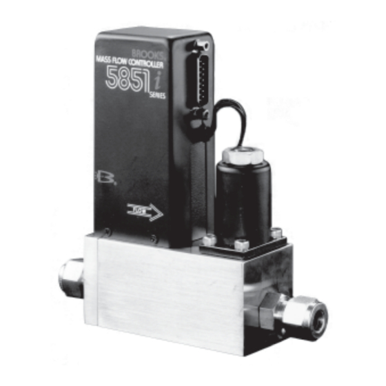
Model 5851i. 1-2 Description The Brooks Model 5851i Mass Flow Controller is used where manual, electronic or computer controlled gas handling occurs. The Model 5851i consists of three basic units: a flow sensor, a control valve and an integral electronic control system. -
Page 9: Command Steps, Soft Start Disabled
X-TMF-5851i-MFC-eng Part Number: 541B109AAG ® Brooks Model 5851i September, 2009 Figure 1-1 Command Steps, Soft Start Disabled Figure 1-2 0 - 100% Command Step, Soft Start Enabled Artisan Technology Group - Quality Instrumentation ... Guaranteed | (888) 88-SOURCE | www.artisantg.com... -
Page 10: Specifications
Section 1 Introduction Installation and Operation Manual X-TMF-5851i-MFC-eng Part Number: 541B109AAG ® Brooks Model 5851i September, 2009 1-3 Specifications Standard Ranges Any full scale flow rate from 10 slpm to 100 slpm (nitrogen equivalent); up to 200 slpm hydrogen. Accuracy ±1% full scale including linearity at calibration conditions... - Page 11 Section 1 Introduction Installation and Operation Manual X-TMF-5851i-MFC-eng Part Number: 541B109AAG ® Brooks Model 5851i September, 2009 Leak Integrity 1 x 10 Atm. scc/sec Helium Control Range 50 to 1 Mechanical Connection Interchangeable with most popular mass flow controllers. Refer to Figure 2-1.
-
Page 12: Receipt Of Equipment
E-mail: BrooksEu@BrooksInstrument.com 2-2 Recommended Storage Practice If intermediate or long-term storage is required for equipment as supplied by Brooks Instrument, it is recommended that said equipment be stored in accordance with the following: a. Within the original shipping container. b. Store in a sheltered area with the following conditions: 1. -
Page 13: Return Shipment
Model 5851i September, 2009 2-3 Return Shipment Prior to returning any Brooks equipment to the factory, contact the factory - for a Return Materials Authorization Number (RMA#). This can be obtained at Brooks Instrument, Product Service Department, 407 West Vine Street, Hatfield, PA 19440-0903, or call toll free 1-888-554-FLOW (3569). -
Page 14: Installation
5.86 Figure 2-1 Model 5851i Dimensions Recommended installation procedures: a. The Model 5851i should be located in a clean dry atmosphere rela- tively free from shock and vibration. b. Leave sufficient room for access to the electrical components. c. Install in such a manner that permits easy removal if the instrument requires cleaning. -
Page 15: In-Line Filter
RED/WHT Chassis Ground GRN/WHT BLU/WHT * Brooks Read Out Models 0151, 0152, 0154, 0254 Figure 2-2 D Connector Shielded Cable Hookup Diagram 2-6 In-Line Filter It is recommended that an in-line filter be installed upstream from the controller to prevent the possibility of any foreign material entering the flow sensor or control valve. -
Page 16: Electrical Interfacing
Electrical Hook-up Setpoint (Command) Input The 5851i Mass Flow Controller can be used with a current (4-20 mAdc) or voltage (0-5 Vdc) setpoint. To use the current setpoint, connect the setpoint (+) signal to pin 7 and the setpoint return (-) signal to pin 1 of the D-connector and configure the PC Board per Section 2-7. -
Page 17: Common Electrical Hook-Ups, Voltage I/O Version
Installation and Operation Manual X-TMF-5851i-MFC-eng Part Number: 541B109AAG ® Brooks Model 5851i September, 2009 Figure 2-4 Common Electrical Hook-Ups, Voltage I/O Version Signal Output The flow signal output can be measured as a voltage and a current simultaneously on two different pins of the D-connector. Pin 2 indicates the flowrate with a 0-5 Vdc signal proportional to the mass flow rate. - Page 18 X-TMF-5851i-MFC-eng Part Number: 541B109AAG ® Brooks Model 5851i September, 2009 Figure 2-5 Recommended I/O Wiring Configuration for Current Sugnals (Non-Isolated Power Supply) Figure 2-6 Recommended I/O Wiring Configuration for Current Sugnals (Isolated Power Supply) Artisan Technology Group - Quality Instrumentation ... Guaranteed | (888) 88-SOURCE | www.artisantg.com...
-
Page 19: Configuring The Pc Board
Installation and Operation Manual X-TMF-5851i-MFC-eng Part Number: 541B109AAG ® Brooks Model 5851i September, 2009 Chassis Ground Connect earth ground to pin 14 of the D-connector. Valve Override (connection optional) The valve override function allows full opening and closing of the valve independent of the setpoint: To open the valve, apply +22.5 to +28 Vdc to pin 12... -
Page 20: Theory Of Operation
The span adjustment in the electronics affects the fine adjustment of the controller's full scale flow. In addition to the mass flow sensor, the Model 5851i Mass Flow Controller has an integral control valve and control circuit, as shown in Figure 3-2. -
Page 21: Operating Procedure
X-TMF-5851i-MFC-eng Part Number: 541B109AAG Brooks ® Model 5851i September, 2009 Figure 3-1 Flow Sensor Operational Diagram Soft Start enabled by moving a jumper on the PC Board. This circuit provides a slow injection of the gas as a protection to the process, particularly those using a volatile or reactive gas. -
Page 22: Zero Adjustment
Figure 3-2 Flow Control System Block Diagram 3-3 Zero Adjustment Each 5851i is factory adjusted to provide a zero ±10 mVdc signal or a 4 mAdc ±0.05 mAdc signal at zero flow. The adjustment is made in our calibration laboratory which is temperature controlled to 21.1°C (70°F ±2°F). -
Page 23: Calibration Procedure
NOTE 2: Calibration of the 5851i mass flow controller requires the use of a digital voltmeter (DVM) and a precision flow standard calibrator such as the Brooks Vol-U-Meter. It is recommended that the calibration be performed only by trained and qualified service personnel. - Page 24 X-TMF-5851i-MFC-eng Part Number: 541B109AAG ® Brooks Model 5851i September, 2009 f. Connect the DVM positive lead to TP1 (100x sensor voltage) and the negative lead to TP4 (circuit common). The setpoint should still be set at 100% flow (5.000V). Measure the flow rate using suitable volumetric calibration equipment.
-
Page 25: Response
Refer to Section 4-7. 3-5 Response Fast Response Adjustment Two methods of adjusting the step response of the 5851i mass flow controllers can be used. Method Number 1 describes a procedure that will get the step response close to optimum quickly and without any flow measuring equipment. -
Page 26: Pc Board Jumper Location & Function
Section 3 Operation Installation and Operation Manual X-TMF-5851i-MFC-eng Part Number: 541B109AAG ® Brooks Model 5851i September, 2009 Figure 3-3 PC Board Jumper Location & Function Artisan Technology Group - Quality Instrumentation ... Guaranteed | (888) 88-SOURCE | www.artisantg.com... -
Page 27: Model 5851I Calibration Connections
Section 3 Operation Installation and Operation Manual X-TMF-5851i-MFC-eng Part Number: 541B109AAG Brooks ® Model 5851i September, 2009 Figure 3-4 Model 5851i Calibration Connections Figure 3-5 Adjustment Potentiometer Location Artisan Technology Group - Quality Instrumentation ... Guaranteed | (888) 88-SOURCE | www.artisantg.com... - Page 28 (500 millisecond response to be within 0.2% of final value or better) in series with the 5851i and a storage oscilloscope or recorder. a. Allow the flow controller to stabilize at 0% setpoint for at least thirty seconds.
- Page 29 Section 3 Operation Installation and Operation Manual X-TMF-5851i-MFC-eng Part Number: 541B109AAG Brooks ® Model 5851i September, 2009 THIS PAGE WAS INTENTIONALLY LEFT BLANK 3-10 Artisan Technology Group - Quality Instrumentation ... Guaranteed | (888) 88-SOURCE | www.artisantg.com...
-
Page 30: General
Brooks Model 5851i September, 2009 4-1 General No routine maintenance is required on the Model 5851i other than an occasional cleaning. If an in-line filter is used, the filtering element should periodically be replaced or ultrasonically cleaned. 4-2 Troubleshooting Artisan Technology Group - Quality Instrumentation ... Guaranteed | (888) 88-SOURCE | www.artisantg.com... - Page 31 September, 2009 A. System Checks The 5851i is generally used as a component in gas handling systems which can be quite complex. This can make the task of isolating a malfunction in the system a difficult one. An incorrectly diagnosed malfunction can cause many hours of unnecessary downtime.
- Page 32 Section 4 Maintenance Installation and Operation Manual X-TMF-5851i-MFC-eng & Troubleshooting Part Number: 541B109AAG ® Brooks Model 5851i September, 2009 Table 4-1 Bench Troubleshooting Trouble Possible Cause Check/Corrective Action Actual flow overshoots setpoint by Anticipate potentiometer out of adjustment. Adjust anticipate potentiometer. Refer to Section 3-5 .
-
Page 33: Torque Sequence For The Valve Retainer Plate
Refer to Section 3-4. NOTE: Do not attempt to disassemble the sensor. D. Cleaning Procedures Should the Model 5851i Mass Flow Controller require cleaning due to deposition, use the following procedures: 1. Remove the unit from the system. - Page 34 & Troubleshooting Part Number: 541B109AAG ® Brooks Model 5851i September, 2009 Table 4-2 Sensor Troubleshooting An alternate method for flushing out the sensor is to replace the restrictor element with a low flow plug restrictor. This plug forces all the flow through the sensor and may dislodge any obstructions.
-
Page 35: Valve Adjusting Spacer Locations
Section 4 Maintenance Installation and Operation Manual & Troubleshooting X-TMF-5851i-MFC-eng Part Number: 541B109AAG Brooks ® Model 5851i September, 2009 Figure 4-2 Valve Adjusting Spacer Locations Artisan Technology Group - Quality Instrumentation ... Guaranteed | (888) 88-SOURCE | www.artisantg.com... -
Page 36: Sensor Tube
Assembly. If the sensor assembly is cleaned and reinstalled, a calibration check should be performed. Refer to Section 3-4. 4-4 Disassembly and Assembly The Model 5851i Mass Flow Controller may be disassembled in the field by the user for cleaning, reranging or servicing. Disassemble and assemble the controller as follows: NOTE: The 5851i Mass Flow Controller should be disassembled and assembled in a clean environment to prevent particulate contamination. -
Page 37: Voltmeter Connections For Valve Adjustment
NOTE: Do not attempt to disassemble the sensor assembly. 11. Remove the sensor assembly O-rings (17) from the flow controller body (14). Using the Brooks O-ring removal tool will help prevent scratching the sealing surface. Artisan Technology Group - Quality Instrumentation ... Guaranteed | (888) 88-SOURCE | www.artisantg.com... -
Page 38: Controller Body
X-TMF-5851i-MFC-eng & Troubleshooting Part Number: 541B109AAG ® Brooks Model 5851i September, 2009 12. Remove the adapter fittings and O-rings (27) from the flow controller body (14). 13. Remove the four screws (29) from the end block (28) and carefully remove the end block. - Page 39 12. Prior to installation, leak and pressure test to any applicable pressure requirements. C. Adjusting the Control Valve The 5851i control valve has been factory adjusted to insure proper operation. Readjustment is only required if any of the following parts have been replaced:...
-
Page 40: Use Of The Conversion Tables
X-TMF-5851i-MFC-eng & Troubleshooting Part Number: 541B109AAG ® Brooks Model 5851i September, 2009 c. Disassemble the control valve following the procedure given in Section 4-4A above. Note the number, locations and thicknesses of all spacers (9 and 10). d. Decrease the preload of the valve by 0.005 inches by either removing a 0.005-inch small preload spacer or by adding a 0.005-inch large... -
Page 41: Use Of Orifice Sizing Nomograph
Installation and Operation Manual & Troubleshooting X-TMF-5851i-MFC-eng Part Number: 541B109AAG Brooks ® Model 5851i September, 2009 Example: The controller is calibrated for Nitrogen. The desired gas is Carbon Dioxide. The output reading is 75 sccm when Carbon Dioxide is flowing. -
Page 42: Conversion Factors (Nitrogen Base)
Section 4 Maintenance Installation and Operation Manual X-TMF-5851i-MFC-eng & Troubleshooting Part Number: 541B109AAG ® Brooks Model 5851i September, 2009 Table 4-3. Conversion Factors (Nitrogen Base). GAS NAME FORMULA SENSOR ORIFICE DENSITY FACTOR FACTOR (kg/m Acetylene 0.615 0.970 1.173 Mixture 0.998 1.018... - Page 43 Section 4 Maintenance Installation and Operation Manual & Troubleshooting X-TMF-5851i-MFC-eng Part Number: 541B109AAG Brooks ® Model 5851i September, 2009 Table 4-3. Conversion Factors (Nitrogen Base) Continued. GAS NAME FORMULA SENSOR ORIFICE DENSITY FACTOR FACTOR (kg/m Hydrogen 1.008 0.269 0.090 Hydrogen Bromide 0.987...
- Page 44 Installation and Operation Manual X-TMF-5851i-MFC-eng & Troubleshooting Part Number: 541B109AAG ® Brooks Model 5851i September, 2009 Flow Rate: 100 slpm Outlet Pressure: 30 psig Inlet Pressure: 50 psig 1. Determine Nitrogen equivalent flow rate (refer to Table 4-3). Nitrogen equivalent flow rate (sccm)
- Page 45 Installation and Operation Manual & Troubleshooting X-TMF-5851i-MFC-eng Part Number: 541B109AAG Brooks ® Model 5851i September, 2009 (orifice conversion factor) Nitrogen 20 x 1.439 28.34 slpm Nitrogen 2. If inlet and outlet pressures are given in gauge pressure (psig) add 14.7 to convert to absolute pressure (psia).
-
Page 46: Example Nomograph
Installation and Operation Manual X-TMF-5851i-MFC-eng & Troubleshooting Part Number: 541B109AAG ® Brooks Model 5851i September, 2009 Figure 4-4 Example Nomograph Table 4-4 5851i Restrictor Selection Guide. Range Restrictor slpm Nitrogen Element Equivalent Flow* Combination Part Number 4.6 to 15 1-40 micron (1 inch) -
Page 47: Model 5851I Orifice Sizing Nomograph
Section 4 Maintenance Installation and Operation Manual & Troubleshooting X-TMF-5851i-MFC-eng Part Number: 541B109AAG Brooks ® Model 5851i September, 2009 Table 4-5 Model 5851i Orifice Sizing Nomograph 4-18 Artisan Technology Group - Quality Instrumentation ... Guaranteed | (888) 88-SOURCE | www.artisantg.com... -
Page 48: Model 5851I Restrictor Element Assembly
Part Number: 541B109AAG ® Brooks Model 5851i September, 2009 Figure 4-6 Model 5851i Restrictor Element Assembly Figure 4-7 Model 5851i Restrictor Element Orientation in Controller Body 4-19 Artisan Technology Group - Quality Instrumentation ... Guaranteed | (888) 88-SOURCE | www.artisantg.com... -
Page 49: Restrictor Sizing
Restrictor O-ring, refer to the spare parts Section 5 for the correct part number. The 5851i Mass Flow Controller utilizes porous metal restrictor assemblies for all full scale flow rates. Restrictor elements with porosities of 40 and 60 microns are used in different combinations. Up to three restrictor elements can be placed in one assembly. - Page 50 X-TMF-5851i-MFC-eng & Troubleshooting Part Number: 541B109AAG ® Brooks Model 5851i September, 2009 Assembly Procedures 1. Select the proper restrictor element combination. 2. When handling restrictor elements, use care to insure that they are not contaminated with dirt, grease, oil, etc. The use of rubber gloves is recommended.
- Page 51 Section 4 Maintenance Installation and Operation Manual & Troubleshooting X-TMF-5851i-MFC-eng Part Number: 541B109AAG Brooks ® Model 5851i September, 2009 THIS PAGE WAS INTENTIONALLY LEFT BLANK 4-22 Artisan Technology Group - Quality Instrumentation ... Guaranteed | (888) 88-SOURCE | www.artisantg.com...
-
Page 52: General
Section 5 Parts List Installation and Operation Manual X-TMF-5851i-MFC-eng Part Number: 541B109AAG ® Brooks Model 5851i September, 2009 5-1 General When ordering parts, please specify: Brooks Serial Number Model Number Part Description Part Number Quantity (Refer to Figure 5-1 and Tables 5-1 and 5-2). -
Page 53: Model 5851I Parts Drawing
Section 5 Parts List Installation and Operation Manual X-TMF-5851i-MFC-eng Part Number: 541B109AAG ® Brooks Model 5851i September, 2009 Figure 5-1 Model 5851i Parts Drawing Artisan Technology Group - Quality Instrumentation ... Guaranteed | (888) 88-SOURCE | www.artisantg.com... - Page 54 Section 5 Parts List Installation and Operation Manual X-TMF-5851i-MFC-eng Part Number: 541B109AAG ® Brooks Model 5851i September, 2009 Table 5-1 Model 5851i Replacement Parts List (Continued on next page) Item Quantity Description Part Number Jam Nut 573B027ACK Coil Assembly S185Z271AAA...
- Page 55 Section 5 Parts List Installation and Operation Manual X-TMF-5851i-MFC-eng Part Number: 541B109AAG ® Brooks Model 5851i September, 2009 Table 5-1 Model 5851i Replacement Parts List (Continued) Item Quantity Description Part Number Fitting, 1/4" Compression, Swagelok 320B136BMA Fitting, 1/4" Male VCR, Cajon 315Z036BMA Fitting, 1/4"...
- Page 56 CE mærkning af Masse Flow udstyr Dato Januar-1996. Brooks Instrument har gennemført CE mærkning af elektronisk udstyr med succes, i henhold til regulativet om elektrisk støj (EMC direktivet 89/336/EEC). Der skal dog gøres opmærksom på benyttelsen af signalkabler i forbindelse med CE mærkede udstyr.
-
Page 57: Ce Certification Of Mass Flow Equipment
Date January-1996. The Brooks (electric/electronic) equipment bearing the CE mark has been successfully tested to the regulations of the Electro Magnetic Compatibility (EMC directive 89/336/EEC). Special attention however is required when selecting the signal cable to be used with CE marked equipment. - Page 58 Janvier 1996. Messieurs, Les équipements Brooks (électriques/électroniques) portant le label CE ont été testés avec succès selon les règles de la Compatibilité Electromagnétique (directive CEM 89/336/EEC). Cependant, la plus grande attention doit être apportée en ce qui concerne la sélection du câble utilisé pour véhiculer le signal d’un appareil portant le label CE.
- Page 59 CE. Qualità dei cavi di segnale e dei relativi connettori: Brooks fornisce cavi di elevata qualità che soddisfano le specifiche richieste dalla certificazione CE. Se l’utente intende usare propri cavi, questi devono possedere una schermatura del 100%.
- Page 60 Utførelse av signalkabel og tilhørende plugger: • Brooks Instrument tilbyr levert med utstyret egnet kabel som møter de krav som stilles til CE-sertifisering. • Dersom kunden selv velger kabel, må kabel med fullstendig, 100% skjerming av lederene benyttes.
- Page 61 Date : January 1996 Brooks (elektriska / elektronik) utrustning, som är CE-märkt, har testats och godkänts enligt gällande regler för elektromagnetisk kompabilitet (EMC direktiv 89/336/EEC). Speciell hänsyn måste emellertid tas vid val av signalkabel som ska användas tillsammans med CE-märkt utrustning.
- Page 62 Installation and Operation Manual X-TMF-5851i-MFC-eng Part Number: 541B109AAG ® Brooks Model 5851i September, 2009 THIS PAGE WAS INTENTIONALLY LEFT BLANK Artisan Technology Group - Quality Instrumentation ... Guaranteed | (888) 88-SOURCE | www.artisantg.com...
- Page 63 BROOKS SERVICE AND SUPPORT Brooks is committed to assuring all of our customers receive the ideal flow solution for their application, along with outstanding service and support to back it up. We operate first class repair facilities located around the world to provide rapid response and support.
- Page 64 Artisan Technology Group is your source for quality new and certified-used/pre-owned equipment SERVICE CENTER REPAIRS WE BUY USED EQUIPMENT • FAST SHIPPING AND DELIVERY Experienced engineers and technicians on staff Sell your excess, underutilized, and idle used equipment at our full-service, in-house repair center We also offer credit for buy-backs and trade-ins •...
Need help?
Do you have a question about the 5851i and is the answer not in the manual?
Questions and answers