Page 1
Installation and Operation Manual X-TMF-MfS-MFC-eng PN 541-C-061-AAG MF Smart Series November, 2008 Brooks 
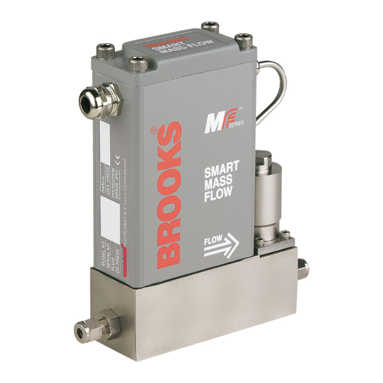
MF Smart Series MFC/MFM ® Smart Mass Flow Controller...
Page 2
We appreciate this opportunity to service your flow measurement and control requirements with a Brooks Instrument device. Every day, flow customers all over the world turn to Brooks Instrument for solutions to their gas and liquid low-flow applications. Brooks provides an array of flow measurement and control products for various industries from biopharmaceuticals, oil and gas, fuel cell research and chemicals, to medical devices, analytical instrumentation, semiconductor manufacturing, and more.
Page 3
Save this instruction manual for future reference. • If you do not understand any of the instructions, contact your Brooks Instrument representative for clarification. • Follow all warnings, cautions and instructions marked on and supplied with the product.
Installation and Operation Manual X-TMF-MfS-MFC-eng PN 541-C-061-AAG MF Smart Series November, 2008 Table of Contents Section 1: Introduction ............................5 1-1 How to use this manual........................5 1.2 Description ............................6 Section 2: Installation .............................. 9 2.1 General ..............................9 2.2 Receipt of equipment ...........................
Denotes that the accompanying text refers to digital communication. Smart Control Digital communication (either via RS-232 or RS-485) allows to connect our Brooks model 0160 Smart Control. This interface program can be used to operate and (re)configure Smart Mass Flow Products (calibration parameters are not accessible).
2160 m³n/h * refers to ‘normal’ conditions, i.e. 0°C, 1013.25 mbar. The Brooks MF-series Smart Mass Flow Meter is a stand-alone instrument with microprocessor-based electronics on board. The MF-series Smart Mass Flow Controller has an integrally-mounted control-valve module with which table gas flows can be achieved.
Page 7
Installation and Operation Manual X-TMF-MfS-MFC-eng Section 1: Introduction PN 541-C-061-AAG MF Smart Series November, 2008 MASS FLOW CONTROLLER Standard features include: • The supplied inlet adapter has a built-in, upstream inlet filter for flow straightening. Besides reducing the effects of changes in upstream piping, this also protects the measuring element from occasional debris in the flow stream.
Page 8
Installation and Operation Manual Section 1: Introduction X-TMF-MfS-MFC-eng PN 541-C-061-AAG MF Smart Series November, 2008 ⇒ Environmental errors - No gas flow detected - Power supply outside specification range - Ambient temperature outside specified range high and low flow alarms •...
If the packing case is damaged, the local carrier should be notified at once regarding his liability. A report should be submitted to your nearest Product Service Department. Brooks Instrument 407 W. Vine Street P.O. Box 903...
PN 541-C-061-AAG MF Smart Series November, 2008 2-4 Return Shipment Prior to returning any instrument to the factory visit the Brooks website www. BrooksInstrument.com for a Return Materials Authorization Number (RMA#), or contact one of the following locations: Brooks Instrument 407 W.
Installation and Operation Manual X-TMF-MfS-MFC-eng Section 2: Installation PN 541-C-061-AAG MF Smart Series November, 2008 2.6 Mechanical Installation (For dimensional drawings see Appendix B: Dimensional drawings) NOTE: When installing the Mass Flow device, care should be taken to prevent foreign materials from entering the instrument’s inlet or outlet. Do not remove the protective end-caps until the actual moment of installation.
Installation and Operation Manual Section 2: Installation X-TMF-MfS-MFC-eng PN 541-C-061-AAG MF Smart Series November, 2008 2.7 In-Line Filter An in-line filter is installed, as standard, in the instrument’s inlet to prevent any foreign material entering the flow sensor or control valve. The filtering element should be periodically replaced or ultrasonically cleaned.
Installation and Operation Manual X-TMF-MfS-MFC-eng Section 2: Installation PN 541-C-061-AAG MF Smart Series November, 2008 Digital communication (pins 1 and 2) (pins 1 and 2) are available for connecting the device to the TxD/A+ or RxD/A-lines for RS-232/RS-485 communications. NOTE: Either RS-232 or RS-485 should be specified at the time of ordering. See section 2.7 for details of how to configure the p.c.
Installation and Operation Manual Section 2: Installation X-TMF-MfS-MFC-eng PN 541-C-061-AAG MF Smart Series November, 2008 Table 2-3: Electrical connection 9-pins terminal Function Controller Meter VSUP 15 Vdc to +28 Vdc Power supply • • SUPCOM Power supply common • • SIGCOM Flow signal output common •...
Installation and Operation Manual X-TMF-MfS-MFC-eng Section 2: Installation PN 541-C-061-AAG MF Smart Series November, 2008 2.9 Electrical interfacing Profibus MF 2.9.1 Main connector (MF series) The MF series have a PG11 connector at the inlet side of the mass flow device for the power supply and analogue I/O.
Installation and Operation Manual Section 2: Installation X-TMF-MfS-MFC-eng PN 541-C-061-AAG MF Smart Series November, 2008 2.9.2 Profibus connector (MF series) The Profibus-DP electronics is hooked up via a separate M12 connector on top of the device. This connector has IP65 protection rate and is defined in the Profibus guideline 2.142: Interconnection Technology Sepecifictions.
Installation and Operation Manual X-TMF-MfS-MFC-eng Section 2: Installation PN 541-C-061-AAG MF Smart Series November, 2008 2.10 Digital Communication NOTE: The printed circuit boards only need to be reconfigured if the hardware settings differ from those specified at the time of ordering. Figure 2-6: p.c.
TXD signal is the output signal of the device and the RxD the input signal. The communication terminals can be directly connected to a serial COM- port of any PC. The other part of the terminals can be connected to Brooks model 0152/0154 Microprocessor-based Readout and Control Electronics.
Installation and Operation Manual X-TMF-MfS-MFC-eng Section 2: Installation PN 541-C-061-AAG MF Smart Series November, 2008 Figure 2-7: RS-232 interconnection of TMFs and PC (not for Profibus) The RS-485 is essentially a multidrop connection. It allows a maximum of 32 devices to be connected to a computer system. IBM-compatible PCs are not equipped with RS-485 ports as standard.
Installation and Operation Manual Section 2: Installation X-TMF-MfS-MFC-eng PN 541-C-061-AAG MF Smart Series November, 2008 2.11 Interconnection with Peripheral Equipment For Profibus communication cable and connectors as specified in Profibus guideline “Profibus interconnection guidelines” document 2.142 for further details refer to Profibus instruction manual. 2.12 Interconnection A shielded cable must be used for interconnection between the device and the pheripheral equipment.
In case Zero adjustment is required, this can be done via Smart Control; model 0160. 3.3 Calibration Procedure Calibration of the Smart MF is not described in this manual. Calibration can only be achieved with use of the accurate Brooks Volumeter equipment and the Smart Service software model; 0163 (see paragraph 4.4).
Installation and Operation Manual X-TMF-MfS-MFC-eng PN 541-C-061-AAG MF Smart Series November, 2008 Section 4: Maintenance 4.1 General No routine maintenance is required on the MF-series Smart Mass Flow Meters and Controllers other than occasional cleaning. The in-line filter should periodically be replaced or ultrasonically cleaned. NOTE: If recalibration is required, but the necessary expertise or equipment is not available, the instrument should be returned to the factory.
Valve override input is grounded Check the valve override input (pin 5 of 9 row) Defective electronic board Contact Brooks Instrument. Output signal stays at approx. 5.25 Valve leaks or is stuck open Clean and/or adjust control valve Vdc or 21 mA (regardless of Set (applicable to MFC) (Section 4.3).
The calibration of MF-series Smart Mass Flow devices is not described in this manual. Such calibration requires the use of accurate and traceable calibration equipment such as Brooks Volumeter equipment, in addition Smart Service software model 0163 is needed. 1. Wetted components include the body, laminar-flow element and all valve components including...
Section 4: Maintenance PN 541-C-061-AAG MF Smart Series November, 2008 However, if the above equipment is available at your facility, then Brooks Instrument will supply you with copy of the calibration procedure document (no.:834-P-088-AAG) upon request. 4.5 Valve (Dis)Assembly Procedure NOTE: If (dis)assembly is required, but the necessary expertise or equipment is not available, then the instrument should be returned to the factory.
Installation and Operation Manual X-TMF-MfS-MFC-eng PN 541-C-061-AAG MF Smart Series November, 2008 Section 5: Specification PERFORMANCE SPECIFICATIONS Flow Accuracy ± 0.7% of rate and ±0.2% f.s. at calibration conditions or ± 0.5% of rate and ±0.1% f.s. at calibration conditions on request ± 1% f.s. for model MF63/53 above 1100 ln/min.
Power Supply, 28 Vdc max., 370 mA for controllers and 90 mA for meters. Protection Grade IP 65 and NEM Table 5-1: Flow ranges and pressure rating Brooks Smart Mass Flow Products Mass Flow Mass Flow Flow Ranges Pressure P.E.D. Controller Meter...
Page 28
Leak Integrity Security To prevent “unauthorized” setting or reranging of span or zero, these functions are only accessible via the Brooks Smart Control, model 0160, or using Smart DDE, model 0162. Warm-up time < 10 minutes; 1% F.S. accuracy. Performance within specifications: 45 minutes.
Page 29
Installation and Operation Manual X-TMF-MfS-MFC-eng Section 5: Specification PN 541-C-061-AAG MF Smart Series November, 2008...
Installation and Operation Manual X-TMF-MfS-MFC-eng PN 541-C-061-AAG MF Smart Series November, 2008 Section 6: Modellisting ENHANCEM ENTS STA NDA RD RESPONSE:< 1 SEC (MF50/51) < 3 SEC (MF53) [1]. FA ST RESPONSE (SPECIFY V A LUES ..SEC.) [1] LINEA R RA MP (SPECIFY V A LUES ..%/SEC.) [1] FLOW OUTPUT DA MPING (SPECIFY V A LUES ..
Page 33
Installation and Operation Manual X-TMF-MfS-MFC-eng Section 6: Modellisting PN 541-C-061-AAG MF Smart Series November, 2008 " 2 o i t " f " " 2 " 1 " 4 " 2 - " - " - " - " - " - "...
Page 34
Installation and Operation Manual Section 6: Modellisting X-TMF-MfS-MFC-eng PN 541-C-061-AAG MF Smart Series November, 2008 O-RING/V ALV E SEAT M ATERIAL V ALV E TYPE > < ELECTRICAL INPUT/OUTPUT INPUT OUTPUT & & & & COM M UNICATION / BAUDRATE NONE (Communication w ill be possible via RS/232 and 9600 baud) RS232 RS485...
Page 35
Installation and Operation Manual X-TMF-MfS-MFC-eng Section 6: Modellisting PN 541-C-061-AAG MF Smart Series November, 2008 ENHANCEM ENTS STA NDA RD RESPONSE:< 1 SEC (MF50/51) < 3 SEC (MF53) [1]. FA ST RESPONSE (SPECIFY V A LUES ..SEC.) [1] LINEA R RA MP (SPECIFY V A LUES ..%/SEC.) [1] FLOW OUTPUT DA MPING (SPECIFY V A LUES ..
This scale shift can be calculated by using the ratio of the molar specific heat of the two gases, or the sensor conversion factor. The gasconversion table is available at Brooks Instrument under document no.: J-836-D-508.
Installation and Operation Manual X-TMF-MfS-MFC-eng Appendix A PN 541-C-061-AAG MF Smart Series November, 2008 Gas Conversion Table Gas Conversion Table: (Source J-836-D-508 Rev. 14) c i f y t i f i r f i r f i r Brom otrifluorom ethane (f-13B1) CBrF3 0,412 2,303...
Page 38
Installation and Operation Manual Appendix A X-TMF-MfS-MFC-eng PN 541-C-061-AAG MF Smart Series November, 2008 Gas Conversion Table (continued) c i f y t i 0,257 2,654 8,814 Hexafluoroethane (f-116) C2F6 0,255 2,219 6,139 Hexafluoropropylene (HFP) C3F6 0,249 2,312 6,663 Hexam ethyldis ilane (HMDS) (CH2)6Si2 0,139 2,404...
Page 39
Installation and Operation Manual X-TMF-MfS-MFC-eng Appendix A PN 541-C-061-AAG MF Smart Series November, 2008 Gas Conversion Table (continued) c i f y t i Perfluorom ethyl-vinylether (PMVE) PMVE 0,296 2,029 5,131 Phos phorous Pentafluoride 0,346 2,109 5,62 f i r Propane (s am e as CH3CH2CH3) C3H8 0,343...
Dansk Brooks Instrument har gennemført CE mærkning af elektronisk udstyr med succes, i henhold til regulativet om elektrisk støj (EMC direktivet 89/336/EEC). Der skal dog gøres opmærksom på benyttelsen af signalkabler i forbindelse med CE mærkede udstyr.
Page 43
La pantalla deberá conectarse a tierra. Français Les équipements Brooks (électriques/électroniques) portant le label CE ont été testés avec succès selon les règles de la Compatibilité Electromagnétique (directive CEM 89/336/EEC). Cependant, la plus grande attention doit être apportée en ce qui concerne la sélection du câble utilisé pour véhiculer le signal d’un appareil portant le label CE.
Page 44
CE. Qualità dei cavi di segnale e dei relativi connettori: Brooks fornisce cavi di elevata qualità che soddisfano le specifiche richieste dalla certificazione CE. Se l’utente intende usare propri cavi, questi devono possedere una schermatura del 80%. I connettori sia di tipo “D” che circolari devono possedere un guscio metallico. Se esiste un passacavo esso deve essere metallico e fornito di fissaggio per lo schermo del cavo.
Page 45
November, 2008 Nederlands Alle CE gemarkeerde elektrische en elektronische produkten van Brooks Instrument zijn met succes getest en voldoen aan de wetgeving voor Electro Magnetische Compatibiliteit (EMC wetgeving volgens 89/336/EEC). Speciale aandacht is echter vereist wanneer de signaalkabel gekozen wordt voor gebruik met CE gemarkeerde produkten.
Page 46
Suoja on oltava maadoitettu. Svensk Brooks (elektriska / elektronik) utrustning, som är CE-märkt, har testats och godkänts enligt gällande regler för elektromagnetisk kompabilitet (EMC direktiv 89/336/EEC). Speciell hänsyn måste emellertid tas vid val av signalkabel som ska användas tillsammans med CE-märkt utrustning.
Please make sure that the process line pressure is removed prior to service. Please make sure that original parts of Brooks are used when the device requires servicing. Note however that look-alike substitutions and procedures can affect the product’s performance and place the save operation of your process at risk.
Page 48
SUOMI TURVAOHJEET Tämä liite sisältää tärkeitä turva- ja käyttöohjeita Brooks:Thermal Mass Flow Meter / Controller Series Instrumentit kuuluvat CE-direktiiviin (PED) PRESSURE EQUIPMENT CE DIRECTIVE 97/23/EC. Kysy lisää paikallisilta viranomaisilta koskien kansainvälisiä ja/tai paikallisia turvakoodeja sekä muita asennusvaatimuksia.
Page 49
WICHTIGE SICHERHEITSHINWEISE Dieser Anhang enthält wichtige Hinweise für einen sicheren Betrieb des Ganzmetall-Schwebekörperdurchfluss-messers der Baureihe Thermal Mass Flow Meter / Controller Series von Brooks Instrument . Das Gerät entspricht den gültigen PED-Richtlinien (PRESSURE EQUIPMENT CE DIRECTIVE 97/23/EC). Konsultieren Sie lokale Zulassungsbehörden für nationale und/oder regionale Sicherheitsbestimmungen bzw.
Page 50
Påse at prosesstrykket er avlastet før utstyret demonteres. Bruk alltid Brooks original deler ved service. Merk at selv om erstatningene ser like ut kan de påvirke produktets virkemåte og gjøre prosessen usikker. Det kan videre føre til brann, elektrisk risiko eller feil virkemåte.
Page 51
Este apéndice contiene importantes instrucciones de operación y seguridad para el uso de los rotámetros de tubo de vidrio BROOKS de la Thermal Mass Flow Meter / Controller. El instrumento es conforme a la directiva 97/23/CE sobre Equipos a Presión de la Comunidad Europea (PED). Consulte con sus autoridades locales por si existieran normas ó...
Page 52
BROOKS SERVICE AND SUPPORT Brooks is committed to assuring all of our customers receive the ideal flow solution for their application, along with outstanding service and support to back it up. We operate first class repair facilities located around the world to provide rapid response and support.
Need help?
Do you have a question about the MFM and is the answer not in the manual?
Questions and answers