Table of Contents
Troubleshooting

Subscribe to Our Youtube Channel
Related Manuals for Brooks SLA7840


Summary of Contents for Brooks SLA7840
- Page 1 Installation and Operation Manual X-PR-SLA7800-RT-eng Part Number: 541B048AAG Model SLA7840 August, 2009 ® Brooks Model SLA7840 Remote Transducer Pressure/Flow Controller Model SLA7840D Digital I/O DeviceNet Model SLA7840A Analog I/O...
- Page 2 Essential Instructions Read this page before proceeding! Brooks Instrument designs, manufactures and tests its products to meet many national and international standards. Because these instruments are sophisticated technical products, you must properly install, use and maintain them to ensure they continue to operate within their normal specifications.
- Page 3 We appreciate this opportunity to service your flow measurement and control requirements with a Brooks Instrument device. Every day, flow customers all over the world turn to Brooks Instrument for solutions to their gas and liquid low-flow applications. Brooks provides an array of flow measurement and control products for various industries from biopharmaceuticals, oil and gas, fuel cell research and chemicals, to medical devices, analytical instrumentation, semiconductor manufacturing, and more.
- Page 4 Installation and Operation Manual X-PR-SLA7800-RT-eng Part Number: 541B048AAG Model SLA7840 August, 2009 THIS PAGE WAS INTENTIONALLY LEFT BLANK...
-
Page 5: Table Of Contents
Installation and Operation Manual Contents X-PR-SLA7800-RT-eng Part Number: 541B048AAG Model SLA7840 August, 2009 Section 1 Introduction Paragraph Page Number Number Scope ............................... 1-1 Purpose ............................1-1 Description ............................1-1 Specifications ........................... 1-2 Section 2 Installation General ............................. 2-1 Receipt of Equipment ........................2-1 Recommended Storage Practice ...................... - Page 6 15-Pin D-Connector Shielded Cable Hookup Diagram - Voltage I/O Version ........2-6 Common Electrical Hookups for 15-Pin D-Connector Voltage I/O Version ........2-6 Flow sensor Operational Diagram ....................3-2 Model SLA7840 System Block Diagram ................... 3-3 Typical Application for Downstream Controller ................. 3-3 Typical Application for Upstream Controller ..................3-4 Externally Accessible Adjustment .....................
-
Page 7: Section 1 Introduction
PID control electronics and a control valve, maintains a desired set pressure. In addition to the pressure function, the Model SLA7840 provides a 0-5 V signal that is linear with mass flow rate. The Model SLA7840 can also be configured as a mass flow controller for calibration or test purposes. -
Page 8: Specifications
Model SLA7840 August, 2009 Broad Array of Communication Options Brooks offers the Model SLA7840 with a traditional 0-5 volt analog option. Brooks also offers control interface with DeviceNet , a high-speed (up to 500k baud) digital communication network. Brooks’ communication capabilities and device-profiles have been certified by the ODVA (Open DeviceNet Vendor’s Association). - Page 9 Section 1 Introduction Installation and Operation Manual X-PR-SLA7800-RT-eng Part Number: 541B048AAG Model SLA7840 August, 2009 Analog I/O Pin Connections for 15-pin D-Connector: Flow Temperature Sensitivity Zero: Less than 0.035% F.S. per Span: Less than 0.1% of rate per Flow Settling Time Less than 1 second to within ±2% full scale of final value for a...
- Page 10 Section 1 Introduction Installation and Operation Manual X-PR-SLA7800-RT-eng Part Number: 541B048AAG Model SLA7840 August, 2009 PHYSICAL: Materials of Construction 316L (VAR), 316L, and high-alloy ferritic stainless steel. External/internal seals: Nickel Valve seat: 316L stainless steel - standard Internal Wetted Surface Finish: 32 Ra maximum...
- Page 11 Section 1 Introduction Installation and Operation Manual X-PR-SLA7800-RT-eng Part Number: 541B048AAG Model SLA7840 August, 2009 Power Requirements: Watts, typical Watts, max. Analog I/O option DeviceNet I/O option Setpoint Input (Analog I/O option only) 0-5 Vdc: Input will accept signals to 5.5 Vdc (110% F.S.).
-
Page 12: Model Sla7840A Analog I/O Controller With 1/4" Vcr Connections
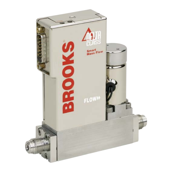
Section 1 Introduction Installation and Operation Manual X-PR-SLA7800-RT-eng Part Number: 541B048AAG Model SLA7840 August, 2009 Figure 1-1 Model SLA7840A Analog I/O Controller with 1/4" VCR Connections Figure 1-2 Model SLA7840D Digital I/O DeviceNet Controller with 1/4" VCR Connections... -
Page 13: Section 2 Installation
Model SLA7840 August, 2009 2-1 General This section provides installation instructions for the Brooks Model SLA7840 Remote Transducer. Figures 1-1 and 1-2 show the Model SLA7840 dimensions, gas connections and electrical connection locations for an RT. 2-2 Receipt of Equipment When the instrument is received, the outside packing case should be checked for damage incurred during shipment. -
Page 14: Return Shipment
Instrument must have been purged in accordance with the following: Completion of form RPR003-1, Brooks Instrument Decontamination Statement. A copy of this form can be downloaded from the Brooks website www.brooksinstrument.com or is available from any Brooks Instrument location listed above. This is required before any Brooks Personnel can begin processing. -
Page 15: Gas Connections
15 microns 2-9 Installation Recommended installation procedures: a. The Model SLA7840 RT should be located in a clean, dry atmosphere relatively free from shock and vibration. b. Leave sufficient room for access to Self-zero function push-button. c. Install in such a manner that permits easy removal if the instrument requires servicing. -
Page 16: Electrical Interface (Analog I/O)
2-10 Electrical Interface (Analog I/O) The Model SLA7840 RT is controlled using analog 0-5 Vdc signals. The minimum set of connections which must be made to the Model SLA7840 RT includes +15 Vdc, supply common, and a setpoint signal. The setpoint signal is supplied as a 0 to 5 Vdc analog signal. -
Page 17: Operation Check Procedure (Analog I/O)
Model SLA7840 August, 2009 NOTICE The Brooks (electric/electronic) equipment bearing the CE mark has been successfully tested to the regulations of the Electro Magnetic Compatibility (EMC directive 89/336/EEC). Special attention is required when selecting the signal cable to be used with CE marked equipment. -
Page 18: Electrical Interface (Devicenet I/O)
Section 2 Installation Installation and Operation Manual X-PR-SLA7800-RT-eng Part Number: 541B048AAG Model SLA7840 August, 2009 2-12 Electrical Interface (DeviceNet I/O) Power and network signals are interfaced to the MFC through the standard 5-pin Micro-connector on the device. This connector is specified in the DeviceNet Specification, Vol. -
Page 19: Section 3 Operation
Section 3 Operation Installation and Operation Manual X-PR-SLA7800-RT-eng Part Number: 541B048AAG Model SLA7840 August, 2009 3-1 Overview This section contains the following information: • Theory of Operation • Functional Description 3-2 Theory of Operation for Flow Measurement The thermal mass flow measurement system consists of two components: the restrictor and the flow sensor. -
Page 20: Theory Of Operation For Remote Transducer
An integral mass flow sensor identical in design to the Brooks Model SLA7840 provides a 5 Vdc full scale signal proportional to the flow through the control valve. -
Page 21: Model Sla7840 System Block Diagram
Section 3 Operation Installation and Operation Manual X-PR-SLA7800-RT-eng Part Number: 541B048AAG Model SLA7840 August, 2009 Figure 3-2 Model SLA7840 System Block Diagram Figure 3-3 Model Typical Application of Downstream Controller... -
Page 22: Analog Mode Of Operation
3-4 Analog Mode of Operation A. Functional Description The analog interface is consistent with other Brooks analog RTs. This includes a 0-5 volt setpoint input, 0-5 volt flow signal output and Valve Override input. Before operating the Model SLA7840, apply power and warm-up the instrument for approximately one hour. -
Page 23: Devicenet Mode Of Operation
The zero process requires approximately 200 msec. During this time, the device will set its output signal to 0.0 Vdc. 3-5 DeviceNet Mode of Operation For information on DeviceNet capabilities for Brooks Model SLA7840 refer to the DeviceNet Supplemental Instruction Manual (X-DPT-DeviceNet- SLA7000-RT-eng). -
Page 24: Calibration Data Sets
Figure 3-5 Externally Accessible Adjustment 3-6 Calibration Data Sets The Model SLA7840 is capable of storing up to 10 sets of gas calibration data in either analog or DeviceNet modes of operation. In the analog mode, the user must use the Brooks Service Tool to switch between the various active gas calibration data sets. -
Page 25: Section 4 Maintenance & Troubleshooting
Part Number: 541B048AAG Model SLA7840 August, 2009 4-1 Overview No routine maintenance is required on the Model SLA7840. If an in-line filter is used, the filtering elements should be periodically replaced. This section provides the following information: • Troubleshooting • Application Information... - Page 26 Failure of the flow rate or flow signal to achieve the setpoint could be caused by a number of factors: 1. Insufficient pressure drop across the Model SLA7840 RT (low or no pressure). If there is not enough pressure differential across the RT, it is impossible for the RT’s valve orifice to pass the full scale flow rate.
-
Page 27: Bench Troubleshooting Circuit
Installation and Operation Manual X-PR-SLA7800-RT-eng & Troubleshooting Part Number: 541B048AAG Model SLA7840 August, 2009 2. ‘Adaptive valve control’ the RT. The RT contains a function which allows it to learn about its environment. Adaptive valve control helps to match the valve performance to the gas, pressure, and temperature of actual use. - Page 28 Section 4 Maintenance Installation and Operation Manual X-PR-SLA7800-RT-eng & Troubleshooting Part Number: 541B048AAG Model SLA7840 August, 2009 Table 4-1 Sensor Troubleshooting SENSOR SCHEMATIC FUNCTION Heater Upstream Temperature Sensor (Su) Downstream Temperature Sensor (Sd) Sensor Common Heater Common Thermistor Thermistor Remove the sensor connector from the PC Board for this procedure.
-
Page 29: Gas Conversion Factors
This scale shift can be approximated by using the ratio of the molar specific heat of the two gases or by sensor conversion factor. Consult factory or nearest Brooks Instrument rep for a list of sensor conversion factors is given in Table 4-5. To change to a new gas, multiply the output reading by the ratio of the gas factor for the desired gas by the gas factor for the calibration gas used. -
Page 30: Orifice Sizing
Restrictor assembly replacement should be performed only by trained personnel. Consult Factory / Service center. Restrictors The Model SLA7840 remote transducer controller uses two types of restrictor assemblies depending on full scale flowrate and expected service conditions. 1. Wire mesh for Nitrogen equivalent flow rates above 3.4 slpm. These restrictor assemblies are made from a cylinder of wire mesh and are easily cleaned if they become contaminated in service. - Page 31 Nitrogen equivalent flow = 20/.945 = 21.16 slpm Nitrogen. In this example a Size 4 Wire Mesh Assembly would be selected. Table 4-3 Model SLA7840 Standard Restrictors Range SCCM Nitrogen Equivalent Flow Part Number*...
- Page 32 Section 4 Maintenance Installation and Operation Manual X-PR-SLA7800-RT-eng & Troubleshooting Part Number: 541B048AAG Model SLA7840 August, 2009 THIS PAGE INTENTIONALLY LEFT BLANK...
- Page 33 CE mærkning af Masse Flow udstyr Dato Januar-1996. Brooks Instrument har gennemført CE mærkning af elektronisk udstyr med succes, i henhold til regulativet om elektrisk støj (EMC direktivet 89/336/EEC). Der skal dog gøres opmærksom på benyttelsen af signalkabler i forbindelse med CE mærkede udstyr.
- Page 34 Date January-1996. The Brooks (electric/electronic) equipment bearing the CE mark has been successfully tested to the regulations of the Electro Magnetic Compatibility (EMC directive 89/336/EEC). Special attention however is required when selecting the signal cable to be used with CE marked equipment.
- Page 35 Janvier 1996. Messieurs, Les équipements Brooks (électriques/électroniques) portant le label CE ont été testés avec succès selon les règles de la Compatibilité Electromagnétique (directive CEM 89/336/EEC). Cependant, la plus grande attention doit être apportée en ce qui concerne la sélection du câble utilisé pour véhiculer le signal d’un appareil portant le label CE.
- Page 36 E’ richiesta comunque una speciale attenzione nella scelta dei cavi di segnale da usarsi con la strumentazione soggetta a marchio Qualità dei cavi di segnale e dei relativi connettori: Brooks fornisce cavi di elevata qualità che soddisfano le specifiche richieste dalla certificazione CE. Se l’utente intende usare propri cavi, questi devono possedere una schermatura del 100%.
- Page 37 Januar 1996 Til den det angår Brooks Instrument elektrisk og elektronisk utstyr påført CE-merket har gjennomgått og bestått prøver som beskrevet i EMC forskrift om elektromagnetisk immunitet, direktiv 89/336/EEC. For å opprettholde denne klassifisering er det av stor viktighet at riktig kabel velges for tilkobling av det måletekniske utstyret.
- Page 38 Date : January 1996 Brooks (elektriska / elektronik) utrustning, som är CE-märkt, har testats och godkänts enligt gällande regler för elektromagnetisk kompabilitet (EMC direktiv 89/336/EEC). Speciell hänsyn måste emellertid tas vid val av signalkabel som ska användas tillsammans med CE-märkt utrustning.
- Page 39 Installation and Operation Manual X-PR-SLA7800-RT-eng Part Number: 541B048AAG Model SLA7840 August, 2009 THIS PAGE WAS INTENTIONALLY LEFT BLANK...
- Page 40 BROOKS SERVICE AND SUPPORT Brooks is committed to assuring all of our customers receive the ideal flow solution for their application, along with outstanding service and support to back it up. We operate first class repair facilities located around the world to provide rapid response and support.
Need help?
Do you have a question about the SLA7840 and is the answer not in the manual?
Questions and answers