
Related Manuals for Afag RM 12


Summary of Contents for Afag RM 12
- Page 1 Rotary module RM 12 - RM 16 - Declaration of Incorporation - Module Information - Montage Instructions - Maintenance Instructions „Translation“ of the Original Montage Instructions © Copyright by Afag Automation AG...
- Page 2 RM 16 11001697 RMZ 16/2 11001700 RM 16-SD 11001702 Version of this documentation: RM 12- RM 16-OI-vers. 2.8 gb. 20190326 Symbols: Assembly and initial start-up must be carried out by qualified Personnel only and according to these Montage Instructions. DANGER Indicates an immediate threatening danger.
-
Page 3: Table Of Contents
1.1.0 According to: 2006/42/EC ................5 2.0.0 Module Information .................... 6 2.1.0 Transport and storage (packing and unpacking) ..........6 2.1.1 Possibilities of fastening RM 12 / RM 16 - Module ......... 7 2.1.2 Centering bushings ..................8 2.1.3 Tightening torques for screw ................9 2.1.4 Preferred combinations RM 12 .............. - Page 4 3.3.4 Proximity Switches ..................45 3.3.5 Mounting for proximity switch ............... 47 4.0.0 Maintenance instructions ................. 48 4.1.0 Maintenance and servicing of the RM 12 / RM 16 ........48 4.1.1 Servicing ...................... 49 4.1.2 Expendable parts RM 12 ................55 4.1.3 Expendable parts RM 16 ................
-
Page 5: Ec Declaration For Incorporation (Document Original)
EC directive: 2006/42 / EC Norme: EN ISO 12100:2010 (German Version) Place, date: Huttwil, 26.03.2019 Siegfried Egli Niklaus Röthlisberger Managing Director Producte Manager HT Afag Automation AG Afag Automation AG RM 12- RM 16-OI-vers. 2.8 gb. 20190326... -
Page 6: Module Information
From the front and from the back 2xM6 NOTE These Montage Instructions should be read carefully before canying out any activity on or with the module. The module may only deployed in accordance with the Intended use. RM 12- RM 16-OI-vers. 2.8 gb. 20190326... -
Page 7: Possibilities Of Fastening Rm 12 / Rm 16 - Module
2.1.1 Possibilities of fastening RM 12 / RM 16 - Module From below 2xM6 From the front and from the back 2xM6 From below 2xM6 There are per modul 3 different . NOTE Use the centering bushings included in the scope of supply for... -
Page 8: Centering Bushings
2.1.2 Centering bushings Hole matrix at the RM 12 / RM 16 rotary module RM 12 RM 16 Hole matrix 48mm Hole matrix 48mm Thread/ bore hole 2xM6 Thread/bore 2xM6 hole Centering 9x4mm Centering 9x4mm bushings (H7) bushings Use the centering bushings included in the scope of supply for positioning and insert these sleeves in the diagonally opposite bore holes of the mounting grid. -
Page 9: Tightening Torques For Screw
Modifications on the RM rotary module that are not described in these Montage Instructions or have not been approved in writing by Afag Automation AG are not permitted. In case of improper changes or assembly, installation, operation and maintenance or repairs Afag rejects all liability RM 12- RM 16-OI-vers. -
Page 10: Preferred Combinations Rm 12
2.1.4 Preferred combinations RM 12 RM 12- RM 16-OI-vers. 2.8 gb. 20190326... -
Page 11: Preferred Combinations Rm 16
2.1.5 Preferred combinations RM 16 RM 12- RM 16-OI-vers. 2.8 gb. 20190326... -
Page 12: Montage Instructions
EC directive: 2006/42/EC Standard: EN ISO 12100:2010 (German version) Agent: For the compilation of the technically relevant documents: Niklaus Röthlisberger, Products Manager Afag Automation AG, CH-4950 Huttwil RM 12- RM 16-OI-vers. 2.8 gb. 20190326... -
Page 13: Symbols
3.1.2 General description This is an incomplete machine The series of the RM 12 / RM 16 rotary module is used for the linear, smooth movement of rigidly mounted loads under the ambient and Installation conditions defined, see Technical data. The RM 12 / RM 16 Rotary module can be installed in the horizontal or vertical position. -
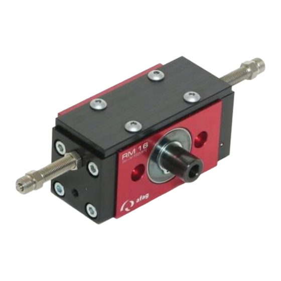
Page 14: Description Rotary Module Rm 12
3.1.3 Description rotary module RM 12 These Montage Instructions describe the rotary modules RM 12 / RM 16 and their variations. All information it these Montage Instructions relates to the above mentioned types. NOTE Special mention is given to type-specific information. - Page 15 RM 12- RM 16-OI-vers. 2.8 gb. 20190326...
-
Page 16: Description The Rotary Module Rm 16
3.1.4 Description the rotary module RM 16 RM 12- RM 16-OI-vers. 2.8 gb. 20190326... - Page 17 RM 12- RM 16-OI-vers. 2.8 gb. 20190326...
-
Page 18: Functional Description
3.1.5 Functional Description RM 12- RM 16-OI-vers. 2.8 gb. 20190326... - Page 19 RM 12- RM 16-OI-vers. 2.8 gb. 20190326...
-
Page 20: Included In The Delivery
Modifications on the module that are not described in these Montage Instructions or have not been approved in writing by Afag are not permitted. In case of improper changes or assembly, installation, operation, maintenance or repairs, Afag rejects al liability. -
Page 21: Warranty
Wear parts (e.g. shock absorbers) are not covered by the warranty. * The warranty covers the replacement or repair of defective Afag parts. No further claims will be accepted. The warranty will be voided in event of the following: ... -
Page 22: Areas Of Application
3.1.9 Areas of application Intended use also includes paying attention to the Montage Instructions and observing the maintenance and repair instructions specified by the manufacturer. The RM 12 / RM 16 module may only be operated and serviced by correspondingly trained personnel who have also profound knowledge of the dangers. -
Page 23: Dimension Rm 12
3.2.0 Dimension RM 12 RM 12- RM 16-OI-vers. 2.8 gb. 20190326... -
Page 24: Technical Data Rm 12
3.2.1 Technical data RM 12 RM 12- RM 16-OI-vers. 2.8 gb. 20190326... -
Page 25: Dimension Rm 16 / Rm 16-Sd / Rmz 16
3.2.2 Dimension RM 16 / RM 16-SD / RMZ 16 RM 12- RM 16-OI-vers. 2.8 gb. 20190326... - Page 26 RM 12- RM 16-OI-vers. 2.8 gb. 20190326...
-
Page 27: Technical Data Rm 16
3.2.3 Technical data RM 16 RM 12- RM 16-OI-vers. 2.8 gb. 20190326... - Page 28 RM 12- RM 16-OI-vers. 2.8 gb. 20190326...
-
Page 29: Dimension Rm 16-Sd/360° - Rmz 16/360
3.2.4 Dimension RM 16-SD/360° - RMZ 16/360° RM 12- RM 16-OI-vers. 2.8 gb. 20190326... -
Page 30: Technical Data Rm 16/360
3.2.5 Technical data RM 16/360° RM 12- RM 16-OI-vers. 2.8 gb. 20190326... -
Page 31: Pneumatic Schematically Rm 12
3.2.6 Pneumatic schematically RM 12 RM 12- RM 16-OI-vers. 2.8 gb. 20190326... -
Page 32: Pneumatic Connections Rm 16
3.2.7 Pneumatic connections RM 16 NOTE Minimal compressed air quality according to ISO 8573-1; 2010 (7-4-4) RM 12- RM 16-OI-vers. 2.8 gb. 20190326... -
Page 33: Pneumatic Connections Rmz 16/2
3.2.8 Pneumatic connections RMZ 16/2 RM 12- RM 16-OI-vers. 2.8 gb. 20190326... -
Page 34: Preparation For Start-Up
3.2.9 Preparation for start-up RM 12- RM 16-OI-vers. 2.8 gb. 20190326... -
Page 35: Rotation Angle Adjustment Rm 12/ Rm 16
3.3.0 Rotation angle adjustment RM 12/ RM 16 RM 12- RM 16-OI-vers. 2.8 gb. 20190326... - Page 36 RM 12- RM 16-OI-vers. 2.8 gb. 20190326...
-
Page 37: Shock Absorbers Sd 08/06
3.3.1 Shock absorbers SD 08/06 RM 12- RM 16-OI-vers. 2.8 gb. 20190326... - Page 38 Adjust shock absorber RM 12- RM 16-OI-vers. 2.8 gb. 20190326...
-
Page 39: Intermediate Positions (Not Monitored)
O-rings here. Process: You have to take modules on the plates 2 black pages and replace it with the new side plates from the set. RM 12- RM 16-OI-vers. 2.8 gb. 20190326... - Page 40 Adjust Intermediate position RM 12- RM 16-OI-vers. 2.8 gb. 20190326...
-
Page 41: Intermediate Position Rmz 16/2 (Monitored)
O-rings here. Process: You have to take modules on the plates 2 black pages and replace it with the new side plates from the set. RM 12- RM 16-OI-vers. 2.8 gb. 20190326... - Page 42 RM 12- RM 16-OI-vers. 2.8 gb. 20190326...
- Page 43 RM 12- RM 16-OI-vers. 2.8 gb. 20190326...
- Page 44 RM 12- RM 16-OI-vers. 2.8 gb. 20190326...
-
Page 45: Proximity Switches
3.3.4 Proximity Switches RM 12- RM 16-OI-vers. 2.8 gb. 20190326... - Page 46 RM 12- RM 16-OI-vers. 2.8 gb. 20190326...
-
Page 47: Mounting For Proximity Switch
3.3.5 Mounting for proximity switch Mounting proximity switch 6,5 mm (Fig.47) RM 12- RM 16-OI-vers. 2.8 gb. 20190326... -
Page 48: Maintenance Instructions
If shock absorbers are missing, defective or incorrectly set up, the functionality of the module will be compromised and may lead to its destruction! 4.1.0 Maintenance and servicing of the RM 12 / RM 16 RM 12- RM 16-OI-vers. 2.8 gb. 20190326... -
Page 49: Servicing
Open guides and piston rods should be covered with a grease layer to avoid formation of rust. Afag standard greasing: - Staburax NBU8EP (flat guides) - Blasolube 301 (piston rods) RM 12- RM 16-OI-vers. 2.8 gb. 20190326... - Page 50 Accessories for RM 12 / RM 16 – Rotary module RM 12- RM 16-OI-vers. 2.8 gb. 20190326...
- Page 51 RM 12- RM 16-OI-vers. 2.8 gb. 20190326...
- Page 52 Accessories 4 Mounting screw 2Side plate 2 O-Ringe RM 12- RM 16-OI-vers. 2.8 gb. 20190326...
- Page 53 RM 12- RM 16-OI-vers. 2.8 gb. 20190326...
- Page 54 RM 12- RM 16-OI-vers. 2.8 gb. 20190326...
-
Page 55: Expendable Parts Rm 12
4.1.2 Expendable parts RM 12 RM 12- RM 16-OI-vers. 2.8 gb. 20190326... -
Page 56: Expendable Parts Rm 16
4.1.3 Expendable parts RM 16 RM 12- RM 16-OI-vers. 2.8 gb. 20190326... -
Page 57: Expendable Parts Rm 16/360
4.1.4 Expendable parts RM 16/360° RM 12- RM 16-OI-vers. 2.8 gb. 20190326... -
Page 58: Expendable Parts Rm 16/360
4.1.5 Expendable parts RM 16/360° RM 12- RM 16-OI-vers. 2.8 gb. 20190326... -
Page 59: Faults During Operation
4.1.6 Faults during operation RM 12- RM 16-OI-vers. 2.8 gb. 20190326... -
Page 60: Disassembly And Repair
Afag Automation AG for repair. NOTE Afag offers a reliable repair service. Please note that Afag does not warranty warranty for parts which were not repaired by Afag Automation AG. -
Page 61: Disposal
5.0.0 Disposal RM 12- RM 16-OI-vers. 2.8 gb. 20190326... -
Page 62: Rm 12- Rm 16-Oi-Vers. 2.8 Gb
RM 12- RM 16-OI-vers. 2.8 gb. 20190326... - Page 63 RM 12- RM 16-OI-vers. 2.8 gb. 20190326...
- Page 64 Afag Automation AG Fiechtenstrasse 32 CH - 4950 Huttwil Switzerland Tel.: +41 62 959 86 86 Fax.: +41 62 959 87 87 e-mail: sales@afag.com Internet: www.afag.com...
Need help?
Do you have a question about the RM 12 and is the answer not in the manual?
Questions and answers