Pilz PSEN sl-0.5p 1.1 Operating Manual
Hide thumbs
Also See for PSEN sl-0.5p 1.1:
- Operating manual (33 pages) ,
- Operating instructions manual (15 pages)
Table of Contents
Advertisement
Advertisement
Table of Contents

Subscribe to Our Youtube Channel
Related Manuals for Pilz PSEN sl-0.5p 1.1


Summary of Contents for Pilz PSEN sl-0.5p 1.1
- Page 1 PSEN sl-0.5p 1.1 PSEN sensor technology Operating Manual-21904-EN-10...
- Page 2 Preface This document is a translation of the original document. All rights to this documentation are reserved by Pilz GmbH & Co. KG. Copies may be made for internal purposes. Suggestions and comments for improving this documentation will be gratefully received.
-
Page 3: Table Of Contents
Connection example PNOZmulti Teaching in the actuator PSEN sl-0.5p 1.1 Installation Note regarding the free-moving actuator PSEN sl-0.5fm Installing on a swing gate Installing on a sliding gate Adjustment Operation Error display through flashing codes Operating Manual PSEN sl-0.5p 1.1 21904-EN-10... - Page 4 Contents Dimensions in mm Technical Details Order No. 570500 Technical Details Order No. 570560 Supplementary data Radio approval Safety characteristic data Order reference Order reference for safety gate system Accessories EC declaration of conformity Operating Manual PSEN sl-0.5p 1.1 21904-EN-10...
-
Page 5: Introduction
PSEN sl-0.5p 1.1 Introduction Validity of documentation This documentation is valid for the product PSEN sl-0.5p 1.1. It is valid until new document- ation is published. This operating manual explains the function and operation, describes the installation and provides guidelines on how to connect the product. -
Page 6: Safety
The following is deemed improper use in particular: Any component, technical or electrical modification to the product Use of the product outside the areas described in this manual Use of the product outside the technical details (see Technical details [ 26]). Operating Manual PSEN sl-0.5p 1.1 21904-EN-10... -
Page 7: Safety Regulations
Are familiar with the basic regulations concerning health and safety / accident preven- tion, Have read and understood the information provided in this description under "Safety" Have a good knowledge of the generic and specialist standards applicable to the spe- cific application. Operating Manual PSEN sl-0.5p 1.1 21904-EN-10... -
Page 8: Warranty And Liability
PSEN sl-0.5fm for special applications with higher tolerance compensation Dual-channel operation 2 safety outputs 2 safety inputs for series connection of multiple safety switches 1 signal output Magnetic guard locking for process protection 1 input to switch the locking magnet on/off Operating Manual PSEN sl-0.5p 1.1 21904-EN-10... -
Page 9: Function Description
There is a low signal at the inputs S11 or S21 or There is a low signal at the input S31 (control command for magnetic guard locking) or The holding force of the locking magnet has not been tested successfully. Operating Manual PSEN sl-0.5p 1.1 21904-EN-10... -
Page 10: Lateral And Vertical Offset
Therefore a higher effort is required when opening for the first time. If the safety gate is in a locked condition and is opened by force, the safety outputs will shut down. Lateral and vertical offset Max. vertical offset: 5 mm Operating Manual PSEN sl-0.5p 1.1 21904-EN-10... -
Page 11: Wiring
Set the supply voltage constantly to the upper tolerance range (see Technical details: System with normal actuator [ 26], System with free-moving actuator [ 29]). Select a higher conductor cross section Reduce load at the outputs, e.g. with evaluation device PNOZ e1.1p Operating Manual PSEN sl-0.5p 1.1 21904-EN-10... -
Page 12: Recommended Cable Cross Sections
Cable type: LiYY 8x0.25 mm² (79 Ohm/km) from Pilz Max. load per safety output 100 mA 500 mA Cable length 65 m 28 m If cable lengths greater than those stated in the table are required, please contact Pilz. Pin assignment 8-pin M12 connector Cable colour (Pilz Function Terminal designation cable) -
Page 13: Connection To Evaluation Devices
Make sure that the selected evaluation device has the following properties: 2-channel with feasibility monitoring OSSD signals are evaluated Connection diagram, single connection 24 V Actuator Safety switch O1 (ST) I1 (FS) I2 (FS) Evaluation device FS: Failsafe ST: Standard Operating Manual PSEN sl-0.5p 1.1 21904-EN-10... - Page 14 Connection diagram, series connection 24 V O1 (ST) Safety switch Actuator I1 (ST) O2 (ST) Safety switch Actuator I2 (ST) O3 (ST) Safety switch Actuator I3 (ST) I1 (FS) I2 (FS) Evaluation device FS: Failsafe ST: Standard Operating Manual PSEN sl-0.5p 1.1 21904-EN-10...
- Page 15 When several units are connected in series, the required current adds with the number of interconnected safety switches. The safety switch PSEN sl-0.5p 1.1 can be connected to Pilz evaluation devices, for ex- ample. Suitable Pilz evaluation devices are, for example:...
-
Page 16: Connection Example Pnoz S3
PSEN sl-0.5p 1.1 Connection example PNOZ s3 PNOZ s3 PSENslock Connection example PNOZmulti PNOZmulti PSENslock green yellow grey Output element, PNOZmulti Legend: Input OSSD Input OSSD Signal input Lock/Unlock Operating Manual PSEN sl-0.5p 1.1 21904-EN-10... -
Page 17: Teaching In The Actuator
PSEN sl-0.5p 1.1 Teaching in the actuator PSEN sl-0.5p 1.1 Any corresponding Pilz actuator (see Technical details: System with normal actuator [ 26], System with free-moving actuator [ 29]) is detected as soon as it is brought into the response range. -
Page 18: Psen Sl-0.5P 1.1
Installation of the safety switch and actuator must be concealed. Alignment errors of the guard must not adversely affect the safety function of the guard. INFORMATION Mounting brackets are available as accessories [ 33]. Operating Manual PSEN sl-0.5p 1.1 21904-EN-10... -
Page 19: Note Regarding The Free-Moving Actuator Psen Sl-0.5Fm
The actuators enable a warped gate to be closed. A gap may occur on the gate as a result. Make sure that the gap remains small enough to exclude the possibility of reaching into the danger zone. Operating Manual PSEN sl-0.5p 1.1 21904-EN-10... -
Page 20: Installing On A Swing Gate
Close gate. Align the mounting bracket flush with the safety switch and tighten the screws. Align the safety switch and mounting bracket with the actuator and tighten the screws. Operating Manual PSEN sl-0.5p 1.1 21904-EN-10... -
Page 21: Installing On A Sliding Gate
Align the safety switch mounting bracket flush with the frame and fasten with screws. (Important: do not tighten the screws) Fix safety switch upright with a screw (a), close gate. Align mounting brackets, press firmly together and tighten screw (b). Operating Manual PSEN sl-0.5p 1.1 21904-EN-10... -
Page 22: Adjustment
"Power / Fault" LED illuminates green: The unit is ready for operation "Safety Gate" LED lights up yellow: Actuator is within the response range "Lock" LED lights up green: Magnetic guard locking device active Operating Manual PSEN sl-0.5p 1.1 21904-EN-10... -
Page 23: Error Display Through Flashing Codes
1 2 3 4 5 6 7 8 9 10 11 12 13 14 15 16 Decimal error code 1 2 3 4 5 6 7 8 9 10 11 12 13 14 15 0 Example: Error code 1,4,1: Flash frequency of the "Safety Gate" or "Input" LED Operating Manual PSEN sl-0.5p 1.1 21904-EN-10... - Page 24 Check cable length and too high (cable is shorten it, if necessary (see too long) max. cable length) Other flashing codes signal an internal error. Remedy: Change device. Operating Manual PSEN sl-0.5p 1.1 21904-EN-10...
-
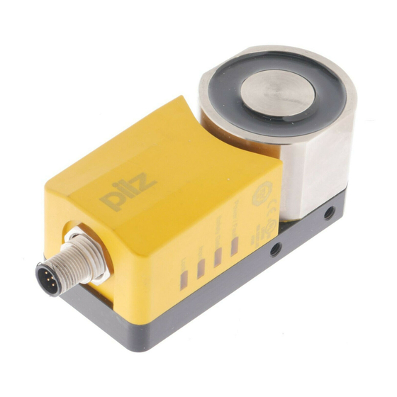
Page 25: Dimensions In Mm
PSEN sl-0.5p 1.1 Dimensions in mm M12x1 Fig.: Safety switch and locking magnet 22,5 Fig.: Actuator Operating Manual PSEN sl-0.5p 1.1 21904-EN-10... -
Page 26: Technical Details Order No. 570500
Coding level in accordance with EN ISO 14119 Design in accordance with EN ISO 14119 Classification in accordance with EN 60947-5-3 PDDB Pilz coding type Coded Transponder Frequency band 122 kHz - 128 kHz Max. transmitter output 15 mW Operating Manual PSEN sl-0.5p 1.1 21904-EN-10... - Page 27 Risk time in accordance with EN 60947-5-3 260 ms Supply interruption before de-energisation 15 ms Simultaneity, channel 1 and 2 max. ∞ Environmental data Temperature of metal surface at ambient temperat- ure: 25 °C 60 °C Operating Manual PSEN sl-0.5p 1.1 21904-EN-10...
- Page 28 Assured operating distance Sao 1 mm Typical operating distance So 2 mm Assured release distance Sar 8 mm Repetition accuracy switching distances 40 % Typ. Hysteresis 0,7 mm Min. distance between safety switches 30 mm Operating Manual PSEN sl-0.5p 1.1 21904-EN-10...
-
Page 29: Technical Details Order No. 570560
15 mW Electrical data Supply voltage Voltage 24 V Kind Voltage tolerance -15 %/+10 % Output of external power supply (DC) 4,8 W Max. inrush current at UB 0,6 A Max. switching frequency 1 Hz Operating Manual PSEN sl-0.5p 1.1 21904-EN-10... - Page 30 25 °C 60 °C Ambient temperature In accordance with the standard EN 60068-2-14 Temperature range -25 - 55 °C Storage temperature In accordance with the standard EN 60068-2-1/-2 Temperature range -25 - 70 °C Operating Manual PSEN sl-0.5p 1.1 21904-EN-10...
- Page 31 Typ. Hysteresis 0,7 mm Min. distance between safety switches 30 mm Sensor flush installation in accordance with EN 60947-5-2 Yes, follow installation guidelines Connection type M12, 8-pin male connector Cable LiYY 8 x 0.25 mm2 Operating Manual PSEN sl-0.5p 1.1 21904-EN-10...
-
Page 32: Supplementary Data
2) this product must accept any interference received, including interference that may cause undesired operation. Changes or modifications made to this product not expressly approved by Pilz may void the FCC authorization to operate this equipment. NOTE: This equipment has been tested and found to comply with the limits for a Class A digital device, pursuant to Part 15 of the FCC Rules. -
Page 33: Safety Characteristic Data
Order reference Order reference for safety gate system Connection Product type Features type Order No. PSEN sl-0.5p 1.1 / PSEN sl-0.5 1 unit Safety gate system, coded M12, 8-pin con- 570 500 nector PSEN sl-0.5p 1.1 / PSEN sl-0.5fm 1 unit Safety gate system, M12, 8-pin con- 570 560... -
Page 34: Ec Declaration Of Conformity
European Parliament and of the Council. The complete EC Declaration of Conformity is available on the Internet at www.pilz.com/downloads. Representative: Norbert Fröhlich, Pilz GmbH & Co. KG, Felix-Wankel-Str. 2, 73760 Ost- fildern, Germany Operating Manual PSEN sl-0.5p 1.1... - Page 35 Back cover Support Technical support is available from Pilz round the clock. Americas Australia Scandinavia Brazil +61 3 95600621 +45 74436332 +55 11 97569-2804 Spain Canada Europe +34 938497433 +1 888-315-PILZ (315-7459) Austria Switzerland Mexico +43 1 7986263-0 +41 62 88979-30...
Need help?
Do you have a question about the PSEN sl-0.5p 1.1 and is the answer not in the manual?
Questions and answers