
Summary of Contents for Code Blue CB 1-w
- Page 1 CB 1-w Solar Tower Model: ENTM06, ENTM07 Admin Guide Installation | Configuration | Support | Maintenance | Use 800.205.7186 • www.codeblue.com...
- Page 2 OF OR IN CONNECTIONS WITH THIS GUIDE, THE SOFTWARE OR OTHER INFORMATION CONTAINED HEREIN OR THE USE THEREOF. Code Blue Corporation reserves the right to make any modifications to this guide or the information contained herein at any time without notice. The software described herein may also be governed by the terms of a separate user license agreement.
-
Page 3: Table Of Contents
CB 1-w Solar Tower Admin Guide Table of Contents Section Section Title Page # Introduction CB 1-w Model Photos Dimensions Safety Information Installation Instructions Getting Started Tools Needed Solar Battery & Solar Panel Prep Anchor Bolt Kit Instructions Deck Mount Kit Instructions... - Page 4 CB 1-w Solar Tower Admin Guide Table of Contents (continued) Section Section Title Page # Complete Solar Tower Diagram - With Audio Paging System Solar Audio Paging Amplifier Wiring Solar Audio Paging Amplifier Connection to Faceplate Speakerphone Solar Panel To Breaker Detail...
-
Page 5: Introduction
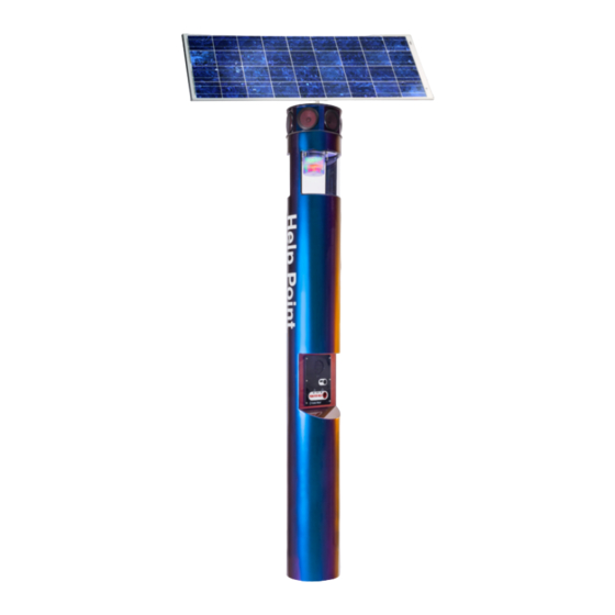
CB 1-w Solar Tower CB 1-w with Solar Tower Solar Audio Paging Array This guide contains all of the CB 1-w Solar Tower information, including: options, application, installation and wiring. Code Blue • 259 Hedcor Street • Holland, MI 49423 USA •... -
Page 6: Dimensions
CB 1-w Solar Tower Admin Guide 3 Dimensions CB 1-w Code Blue • 259 Hedcor Street • Holland, MI 49423 USA • 800.205.7186 • www.codeblue.com GU-168-E page 6 of 53... - Page 7 CB 1-w Solar Tower Admin Guide 3 Dimensions Solar Audio Paging Speaker Array 7.86 6.50 SIDE VIEW 13.00 TOP VIEW Code Blue • 259 Hedcor Street • Holland, MI 49423 USA • 800.205.7186 • www.codeblue.com page 7 of 53 GU-168-E...
-
Page 8: Safety Information
In some countries, a certified electrician may be required. NOTICE When transporting a Code Blue product, use the original packaging or equivalent to prevent damage to the product. Code Blue products shall be used in compliance with local laws and regulations. -
Page 9: Installation Instructions
Important Notes: EIA/TIA, ANSI, CSA and BICSI cabling or similar standards shall be adhered to for proper operation of Code Blue communication devices connected to copper or fiber infrastructures communications cable and electrical cable in the same conduit is not an acceptable installation and shall not be supported. -
Page 10: Tools Needed
CB 1-w Solar Tower Admin Guide Tools Needed All CB 1-w Units Require: Ladder to reach the top of the unit. Drill & Security Bit for removing & inserting security screws on phone, dome top, & access door. 1-1/8” Socket set & extension Phillips and flat head screwdrivers 1/2"... -
Page 11: Solar Battery & Solar Panel Prep
CB 1-w Solar Tower Admin Guide Solar Battery Prep If needed, remove all batteries from enclosure. Using a multimeter, verify the voltage of each battery. The battery voltage should be 12.7 VDC or higher. If the battery voltage is less, charge the battery with a battery charger. -
Page 12: Anchor Bolt Kit Instructions
1.3 Set the Anchor Bolts in the Wet Foundation Four 24-inch L-shaped anchor bolts and an aligning template are supplied for anchoring the Code Blue unit. The bolts should be set into the foundation so that six inches are left showing above the finished grade level. -
Page 13: Deck Mount Kit Instructions
CB 1-w Solar Tower Admin Guide Deck Mount Kit Instructions SKIP if installation does not include a Deck Mount Kit 1. DECK FOUNDATION 1.1 Drill Deck Holes Drill four holes through the deck or floor for the four 3/4” threaded rods. The holes should be aligned, using the tem- plate provided in such a way that the phone faceplate on the unit will face in the desired direction. -
Page 14: Base Gasket Instructions
IMPORTANT: Leveling the bottom nuts is crucial to leveling The bottom edge of the Code Blue unit will be 1/2" above the unit. the concrete when in stalled. A small error will be magnified after installation. -
Page 15: Tower Installation
Moisture problems may result if this condition is not complied with. Set the Code Blue unit on the anchor bolts – Align the phone plate in the desired direction and lift the Code Blue unit over the anchor bolts. The unit may be lifted using the bracket on the inside of the unit. -
Page 16: Solar Audio Paging Installation
CB 1-w Solar Tower Admin Guide Solar Audio Paging Installation SKIP if installation does not include Audio Paging Array NOTE: Prior to beginning the steps below, remove the 6 bolts & washers on top of the Solar Audio Paging Array to remove the top plate. - Page 17 CB 1-w Solar Tower Admin Guide Solar Audio Paging Installation (continued) Re-attach Solar Array Top Plate - Using the 6 bolts & washers that were removed previously, reattach the top plate of the Audio Paging Speaker Array. Fish Cables Through Cord Grips - Pass the solar panel power & cellular antenna cables through the pre-installed cord grips located on the top of the Solar Array Top Plate.
-
Page 18: Solar Audio Paging Amp Connetcion
CB 1-w Solar Tower Admin Guide Solar Audio Paging Installation (continued) Solar Audio Paging Amp Connection 4 Connections From Amp Black & Red 2 Conductor Wire w/ Female Wago Connector – Connect to Amp on 5 Way Manifold Black Wire w/ 7 Pin Connector – Connect to 7 Pin Input on Phone Board (See Figure 2 for phone inputs) Gray 4 Pin RJ 11 Cable- Connect to PAS Audio Input on Phone Board. -
Page 19: Solar Audio Paging Amp - Volume Level Adjustment
CB 1-w Solar Tower Admin Guide Solar Audio Paging Installation (continued) Solar Audio Paging Amp - Volume Level Adjustment Locate Volume Adjustment Knob on Paging Amp - See location in below photo Adjust Volume to Desired Level - By turning the knob clockwise or counter clockwise, this will increase or decrease the volume level of the Audio Paging Speaker Array. -
Page 20: Solar Panel Bracket Installation
CB 1-w tower itself. Attach the aluminum solar panel base mount to the tower – Align the solar panel base gasket over the 3 coordinating holes on the tower. -
Page 21: Solar & Cellular Wiring Installation
Previous versions of the CB 1-w were designed with the solar panel connection wires running through the panel mounting brackets. The current version of the CB 1-w has cord grip pass throughs integrated into the top of the tower. Both installation types are detailed on this page. -
Page 22: Solar Panel Installation
CB 1-w Solar Tower Admin Guide Solar Panel Installation Connect solar panel to mounting bracket - Attach the mounting bracket to the solar panel as shown in Figure 5, using the supplied 1/4"-20 bolts & nylock nuts. Solar Panel 1/4"-20 Bolts... - Page 23 CB 1-w Solar Tower Admin Guide Solar Panel Installation Position the solar panel - The orientation of the solar array is important for proper system performance. In the northern hemisphere the solar array should be pointing true south and in the southern hemisphere the solar array should be pointing true north.
-
Page 24: Cellular Communication Wiring & Antenna Installation
Admin Guide Cellular Communication Wiring & Antenna Installation Shipping - Unless your CB 1-w unit is ordered with an Audio Paging Speaker Array, the Cellular Communication Antenna is shipped pre-installed through the cord grips & wrapped to help reduce install time and protect it during transit. The antenna will be mounted to a specific location on Solar Panel during the following step. - Page 25 CB 1-w Solar Tower Admin Guide Cellular Communication Wiring & Antenna Installation (continued) Mounting Location - On the top edge of the solar panel, locate the “U” shaped slot. This is where the antenna will be mounted. Cellular Antenna Install Location Place the Antenna - Insert the threaded stud located on the bottom of the antenna into the “U”...
- Page 26 CB 1-w Solar Tower Admin Guide Cellular Communication Wiring & Antenna Installation (continued) Slip-On Lock Nut - Slide the supplied slip-on locking nut(Figure 7) around the cables, & secure it tightly to the threaded stud on the antenna. Figure 7 Slip-On Lock Nut The antenna assembly should appear as pictured below when complete.
-
Page 27: Solar Power Installation
CB 1-w Solar Tower Admin Guide Solar Power Installation Fish the wires into the unit and connect them to the battery – Use the existing pull wire and attach the solar panel and antenna wires to pull down into the unit. - Page 28 CB 1-w Solar Tower Admin Guide Solar Power Installation (continued) Remove the faceplate speakerphone & lower access door from the tower – The faceplate speakerphone opening will be utilized to properly used the battery hoist strap. Insert the battery shelf – Using the lower access door opening, place the battery shelf plate on the tabs located inside the tower.
- Page 29 CB 1-w Solar Tower Admin Guide Solar Power Installation (continued) Connect battery leads and terminal covers – Attach the battery leads, starting with the battery terminal that will be the lowest inside the unit. Once the leads are secured, attach the battery terminal covers to prevent shorting against the inside of the tower.
- Page 30 CB 1-w Solar Tower Admin Guide Solar Power Installation (continued) Attach battery hoist strap to first battery – Attach the battery hoist strap to the first battery to be installed, & fish the remaining strap through the access door opening &...
- Page 31 CB 1-w Solar Tower Admin Guide Solar Power Installation (continued) Connect the negative terminal cable to the second battery – Attach the battery cable that previously connected to the negative terminal on the first battery, to the second battery. Repeating previous steps, attach the battery hoist strap to the second battery.
-
Page 32: Speakerphone Installation
IP Faceplate Speakerphone should appear as displayed in the photo below. Once connected, it needs to be secured to the CB 1-w tower using the 6 countersunk security screws and security bit included with the unit. See LS1000 VoIP Speakerphone Admin Guide for programming details. -
Page 33: S-1000 & S-1050 Strobe Operation
CB 1-w Solar Tower Admin Guide S-1000 & S-1050 Strobe Operation NOTE: Instructions pertain to: Model S-1000 LED Beacon/Strobe and Model S-1050 LED Beacon/Strobe only. POSITIVE (12-24V DC or AC) BLACK COMMON (GROUND) YELLOW (FLASH MODE) CONTACT CLOSED = "ON"... - Page 34 CB 1-w Solar Tower Admin Guide PROGRAMMING PRIMARY & SECONDARY MODES 1. Remove power from unit. 2. Short the Yellow wires together. 3. Restore power to the unit and wait until the unit begins to flash. Once the unit begins to flash, remove the short. The unit will alternately demonstrate the Secondary-Flash Mode and Primary-Steadyburn Mode that will be displayed during operation.
-
Page 35: Power Requirements
CB 1-w Solar Tower Admin Guide 6 Power Requirements The following tables on pages 35-38 include CB 1-w and ALL OTHER Code Blue devices & enclosures for reference. Code Blue • 259 Hedcor Street • Holland, MI 49423 USA •... - Page 36 CB 1-w Solar Tower Admin Guide Code Blue • 259 Hedcor Street • Holland, MI 49423 USA • 800.205.7186 • www.codeblue.com page 36 of 53 GU-168-E...
- Page 37 CB 1-w Solar Tower Admin Guide Code Blue • 259 Hedcor Street • Holland, MI 49423 USA • 800.205.7186 • www.codeblue.com page 37 of 53 GU-168-E...
- Page 38 CB 1-w Solar Tower Admin Guide Code Blue • 259 Hedcor Street • Holland, MI 49423 USA • 800.205.7186 • www.codeblue.com page 38 of 53 GU-168-E...
-
Page 39: Wiring Diagrams
CB 1-w Solar Tower Admin Guide 7 Wiring Diagrams Complete Solar Tower Diagram - No Audio Paging System 180W Solar Panel Product wiring diagram shown reasonably represents current offering and is intended to assist in component identification and service. Earlier product production may have different components and wiring connections. -
Page 40: Complete Solar Tower Diagram - With Audio Paging System
CB 1-w Solar Tower Admin Guide Complete Solar Tower Diagram - With Audio Paging System Amp Connection Details on Following Page 180W Solar Panel Product wiring diagram shown reasonably represents current offering and is intended to assist in component identification and service. Earlier product production may have different components and wiring connections. -
Page 41: Solar Audio Paging Amplifier Wiring
CB 1-w Solar Tower Admin Guide Solar Audio Paging Amplifier Wiring Incoming This harness comes with the Amp PCB 12V DC Power SPKR - SPKR + This harness comes with the Amp PCB 360°Audio Paging System Product wiring diagram shown reasonably represents current offering and is intended to assist in component identification and service. Earlier product production may have different components and wiring connections. -
Page 42: Solar Audio Paging Amplifier Connection To Faceplate Speakerphone
CB 1-w Solar Tower Admin Guide Solar Audio Paging Amplifier Connection to Faceplate Speakerphone Code Blue - + - + 1 1 2 2 3 3 1 1 2 2 3 3 PAS Amp enabled LAN port 1 LAN port 2... -
Page 43: Solar Panel To Breaker Detail
CB 1-w Solar Tower Admin Guide Solar Panel To Breaker Detail Connection takes place on Power Control Interface(PCI). Note: This system uses a PCI; the breaker and solar charge controller will be integrated directly into the PCI housing so the solar array will simply connect to the solar leads on the PCI’s terminal block. -
Page 44: Solar Batteries To Breaker Detail
CB 1-w Solar Tower Admin Guide Solar Batteries To Breaker Detail Connection takes place on Power Control Interface(PCI). Note: This system uses a PCI; the breaker and solar charge controller will be integrated directly into the PCI housing so the solar array will simply connect to the solar leads on the PCI’s terminal block. -
Page 45: 110-347V Ac Standard Wiring With Multi-Tap Transformer (Power Brick)
CB 1-w Solar Tower Admin Guide 110-347V AC Standard Wiring with Multi-Tap Transformer (Power Brick) Only for use in instances where a solar powered tower is being converted to line powered unit. Incoming power connection configurations: Incoming Power Connections Located... -
Page 46: Locating Unit Serial Numbers
CB 1-w Solar Tower Admin Guide 8 Locating Unit Serial Numbers Remove the access plate cover with the special security bit. The serial number will be listed on the manufacturer’s label located on the backside of the access plate cover (1). -
Page 47: Troubleshooting
CB 1-w Solar Tower Admin Guide 9 Troubleshooting Common Troubleshooting for Solar Powered Systems Code Blue • 259 Hedcor Street • Holland, MI 49423 USA • 800.205.7186 • www.codeblue.com page 47 of 53 GU-168-E... - Page 48 CB 1-w Solar Tower Admin Guide 10 Definitions Abbreviations, acronyms, & definitions used in this guide Code Blue • 259 Hedcor Street • Holland, MI 49423 USA • 800.205.7186 • www.codeblue.com page 48 of 53 GU-168-E...
-
Page 49: Maintenance Schedule
CB 1-w Solar Tower Admin Guide 11 Maintenance Schedule It is important that the system be regularly maintained to ensure reliable, long-term operation. Code Blue recommends that the Solar Powered system be inspected annually. The inspection should check to make sure all connections are still secure and look for signs of elemental wear or damage due to sun, wind, rain, sand, etc. - Page 50 The Surface Care Frequency table below provides general guidelines to assist in configuring a schedule. Please note that the frequency of care required to guard the Code Blue unit’s surface from damage will also be dictated by local environmental characteristics.
-
Page 51: Warranty
12 Warranty Code Blue Corporation provides a limited warranty on this product. Refer to your sales agreement to establish the terms. In addition, Code Blue’s standard warranty language, as well as information regarding support for this product while under warranty, is available at www.codeblue.com/support... -
Page 52: Download Information
CB 1-w Solar Tower Admin Guide 13 Download Information Code Blue now has a centralized location where you can find installation, setup, information, configuration and operation instructions. Admin Guides: www.codeblue.com/resources/guides Frimware: www.codeblue.com/resources/firmware Maintenance Tips: www.codeblue.com/support Product Sheets: www.codeblue.com/resources/sheets Specifications: www.codeblue.com/resources/specifications These guides should contain all the information needed for your application. -
Page 53: Legal & Regulatory Information
This digital apparatus complies with CAN ICES-3 (Class A). The product shall and fitness for a particular purpose. Code Blue shall not be liable or be connected using a shielded network cable (STP) that is properly responsible for incidental or consequential damages in connection with grounded.
Need help?
Do you have a question about the CB 1-w and is the answer not in the manual?
Questions and answers