Beckhoff CP770 140 Series Installation And Operating Instructions Manual
Ip65 stainless steel panel pc
Hide thumbs
Also See for CP770 140 Series:

Subscribe to Our Youtube Channel
Related Manuals for Beckhoff CP770 140 Series


Summary of Contents for Beckhoff CP770 140 Series
- Page 1 Installation and Operating instructions for CP770x-140x IP65 Stainless steel Panel PC Version: 1.4 Date: 2018-07-11...
-
Page 3: Table Of Contents
Table of contents Table of contents 1 Foreword Notes on the Documentation 1.1.1 Liability Conditions 1.1.2 Trademarks 1.1.3 Patent Pending 1.1.4 Copyright 1.1.5 State at Delivery 1.1.6 Delivery conditions Description of safety symbols Basic safety measures Operator’s obligation to exercise diligence 1.4.1 National regulations 1.4.2... - Page 4 8 Wiring Diagram 9 Technical Data 10 Appendix 10.1 Beckhoff Support and Service 10.1.1 Beckhoff branches and partner companies 10.1.2 Beckhoff company headquarters 10.2 Approvals for USA and Canada 10.3 FCC Approvals for the United States of America 10.4 FCC Approval for Canada...
-
Page 5: Foreword
Modifications to hardware or software configurations other than those described in the documentation are not permitted, and nullify the liability of Beckhoff Automation GmbH & Co. KG. 1.1.6 Delivery conditions In addition, the general delivery conditions of the company Beckhoff Automation GmbH & Co. KG apply. CP770x-140x... -
Page 6: Description Of Safety Symbols
Foreword 1.2 Description of safety symbols The following safety symbols are used in this operating manual. They are intended to alert the reader to the associated safety instructions. Acute risk of injury! If you do not adhere the safety advise adjoining this symbol, there is immediate danger to life and health of individuals! DANGER Risk of injury! -
Page 7: Basic Safety Measures
Foreword 1.3 Basic safety measures Before the Industrial PC is switched off, software that is running must be properly closed. Otherwise it is possible that data on the storage medium is lost. Please read the section Switching the Panel PC on and off. -
Page 8: Operator's Obligation To Exercise Diligence
• the operation manual is in good condition and complete, and always available for reference at the location of the product Do not open the housing of the Panel PC! For technical support contact Beckhoff Service. Note 1.4.1 National regulations Depending on the type of machine and plant in which the Industrial PC is used, national regulations governing the controllers of such machines will apply, and must be observed by the operator. -
Page 9: Product Description
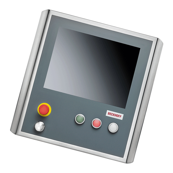
Product Description 2 Product Description 2.1 Product overview Front view of CP770x-1400 Front view of CP770x-1401 with USB-port, emergency stop button and electromechanical push-buttons CP770x-140x... - Page 10 Connectors in the range of the mounting arm adapter: - Two RJ-45-Ethernet-Connectors, 10/100/1000 MBit, IP65 - One 2-Port-USB-Interface - Power Supply • USB-port, emergency stop button and electromechanical push-buttons in the front (only CP770x-1401) • Optionally available: Beckhoff stainless steel mounting arm adapter C9900-M177 and C9900- M178. CP770x-140x...
-
Page 11: Appropriate Use
Product Description 2.2 Appropriate Use The CP770x Panel PC is designed for industrial application in machine and plant engineering. In addition to the integrated PC, a TFT display and a touch screen are accommodated in a stainless steel housing. In the front of the Panel PC CP770x-1401, one USB-port, an emergency stop button (S1) and three electromechanical push-buttons (S2-S4) are integrated. -
Page 12: Access To The Memory Device And The Battery
Product Description After opening the connection area you have access to the connectors of the Panel PC. The cables with the connectors have to be pulled through the mounting arm tube before connecting them in the connection area. The installation of the cover takes place in reverse order. 2.4 Access to the memory device and the battery 2.4.1 Removing the rear cover rear cover... -
Page 13: Replacing The Battery
Product Description Removing the rear cover allows access to the memory devices (1) and the lithium battery of the system clock (2): battery (2) memory devices (1) The memory device can now be pulled out. Here, changing the lithium battery is also possible. The installation takes place in reverse order. -
Page 14: Connections
Product Description 2.5 Connections CP770x-1400 Protective Earthing X102, X103 Ethernet X100 X101 2-Port-USB Power Supply CP770x-1401 with USB-port, emergency stop button and electromechanical push-buttons in the front Protective Earthing X102, X103 Ethernet XS01 X100 Power Supply, emergency 2-Port-USB stop and push-buttons 2.5.1 2-Port-USB-Interface (X100) X100 SG 8POL M9 built-in-PCB-sold. -
Page 15: Power Supply Cp770X-1400 (X101)
Product Description 2.5.2 Power Supply CP770x-1400 (X101) X101 SG 4POL M12- built-in-PCB-sold. IP67 BINDER (BINDER 09-3431-90-04 SERIES 763 M12X1) The power supply for the Panel PC is established via the 4-pole M12 socket (X 101). The protection class of the circular plug-in connector accords to the IP67-standard. Signal + 24V 2.5.3 Power Supply CP770x-1401 (XS01) -
Page 16: Network Interfaces (X102, X103)
Product Description Signal Signal S1.12 LED red K1 S1.11 S1.22 S4.14 S1.21 S4.22 S2.14 LED white K1 S2.22 LED green K1 S3.14 + 24V S3.22 2.5.4 Network Interfaces (X102, X103) RJ-45-Connector (Ethernet 10/100/1000 Mbit) The RJ-45 sockets (X 102, X 103) enable connection of the Panel PC to an 10/100/1000 Mbit Ethernet network. -
Page 17: Usb-Port At The Front (Cp770X-1401)
Product Description 2.5.6 USB-Port at the Front (CP770x-1401) USB-Port Screw cap The Panel PC CP770x-1401 is provided with an additional USB-2.0-port. The port is located at the front side of the Panel PC under a screw cap. The protection class accords to the IP67-standard. -
Page 18: Usb-Adapter Cable
Product Description 2.6.2 USB-adapter cable The provided Y-adapter cable enables connecting two peripheral USB devices to the Panel PC. 2.6.3 Optional Ethernet connection cables The following Ethernet connection cables are available: Patch cable Cable CAT 5, RJ45 connector, second end RJ45 IP67 C9900-K605 Patch cable CAT 5, 5 m length C9900-K606... -
Page 19: Installation
4. Please keep the associated paperwork. It contains important information for handling the unit. 5. Check the contents for visible shipping damage. If you notice any shipping damage or inconsistencies between the contents and your order, you should notify Beckhoff Service. CP770x-140x... -
Page 20: Mounting
Mounting 4 Mounting For mounting the Panel PC there are 6 threaded holes M6 x 6 mm in the range of the mounting arm adapter at the rear side of the chassis (also see chapter Assembly dimensions). Optionally the Panel PC can be mounted with a mounting arm adapter (order option). 4.1 Mounting arm installation Depending on the order option the mounting arm can be installed from the bottom or from the top. -
Page 21: Mounting The O-Rings
Mounting 4.1.2 Mounting the O-rings The junction of the mounting arm adapter has to be fitted with the two red O-rings (see picture). Mounting with PTFE-grease Use assembly PTFE-grease for mounting arm installation. Attention In order to ensure better mobility of the mounting arm adapter, lubricate the O-rings and all parts which have contact with the O-rings with the PTFE-grease. -
Page 22: Mounting The Mounting Arm
Mounting 4.1.3 Mounting the mounting arm Before you can mount the mounting arm at the Panel PC, the screw (1) which fixes the adapter (2) has to be unscrewed and taken out completely. O-rings The picture shows the assembly of the rotatable mounting arm adapter, which first must be frozen with the customized mounting arm (see chapter Welding the mounting arm tube). -
Page 23: Connecting The Panel Pc
Mounting 4.2 Connecting the Panel PC Risk of explosion! The Panel PC must never be connected or disconnected in an area that is subject to explosion hazard! Danger The mains plug must be disconnected Please read the documentation for the external devices prior to connecting them! Attention During thunderstorms, plug connector must neither be inserted nor removed! When disconnecting a plug connector, always handle it at the plug. -
Page 24: Operating Instructions
Operating Instructions 5 Operating Instructions 5.1 Switching the Panel PC on and off 5.1.1 Switching on The Panel PC does not have its own mains power switch. As soon as the power supply is switched on the Panel PC is activated. 5.1.2 Shutting down and switching off Control software, as typically applied in Industrial PCs, enables the assignment of different rights to all users. -
Page 25: Servicing And Maintenance
Operating Instructions 5.3 Servicing and maintenance 5.3.1 Cleaning Disconnect power supply Switch off the device and all connected devices, and disconnect the device from the power supply. DANGER The device can be cleaned with a soft, damp cleaning cloth. Do not use any aggressive cleaning materials, thinners, scouring material or hard objects that could cause scratches. -
Page 26: Troubleshooting
No power supply to Panel PC Check power supply cable Cable not connected Correctly connect cable Call Beckhoff Service Panel PC boots, software starts, but The cause of the error is in the Call the manufacturer of the control does not operate correctly... -
Page 27: Assembly Dimensions
Assembly dimensions 7 Assembly dimensions Notice mounting orientation The assembly of the unit must take place with the orientation diagrammed here. Warning CP770x-140x... - Page 28 Assembly dimensions Notice mounting orientation The assembly of the unit must take place with the orientation diagrammed here. Warning CP770x-140x...
- Page 29 Assembly dimensions Notice mounting orientation The assembly of the unit must take place with the orientation diagrammed here. Warning CP770x-140x...
- Page 30 Assembly dimensions Notice mounting orientation The assembly of the unit must take place with the orientation diagrammed here. Warning CP770x-140x...
- Page 31 Assembly dimensions Notice mounting orientation The assembly of the unit must take place with the orientation diagrammed here. Warning CP770x-140x...
- Page 32 Assembly dimensions Notice mounting orientation The assembly of the unit must take place with the orientation diagrammed here. Warning CP770x-140x...
- Page 33 Assembly dimensions Notice mounting orientation The assembly of the unit must take place with the orientation diagrammed here. Warning CP770x-140x...
- Page 34 Assembly dimensions Notice mounting orientation The assembly of the unit must take place with the orientation diagrammed here. Warning CP770x-140x...
- Page 35 Assembly dimensions Notice mounting orientation The assembly of the unit must take place with the orientation diagrammed here. Warning CP770x-140x...
-
Page 36: Wiring Diagram
Wiring Diagram 8 Wiring Diagram Emergency stop button and electromechanical push-buttons CP770x-140x... -
Page 37: Technical Data
Technical Data 9 Technical Data Risk of explosion! Do not use the Panel PC in areas of explosive hazard! Danger Pixel errors Pixel errors in the TFT display are production-caused and represent no complaint- reason! Note Anomalies of the Touchscreen Anomalies of the touchscreen sensor are production-caused and represent no complaint-reason! Note... -
Page 38: Appendix
Please contact your Beckhoff branch office or partner company for local support and service on Beckhoff products! The contact addresses for your country can be found in the list of Beckhoff branches and partner companies: www.beckhoff.com. You will also find further documentation for Beckhoff components there. -
Page 39: Approvals For Usa And Canada
Appendix 10.2 Approvals for USA and Canada 10.3 FCC Approvals for the United States of America FCC: Federal Communications Commission Radio Frequency Interference Statement This equipment has been tested and found to comply with the limits for a Class A digital device, pursuant to Part 15 of the FCC Rules.
Need help?
Do you have a question about the CP770 140 Series and is the answer not in the manual?
Questions and answers