Beckhoff Economy CP72 Series Installation And Operating Instructions Manual
Hide thumbs
Also See for Economy CP72 Series:
- Installation and operating instructions manual (31 pages) ,
- Manual (48 pages)

Related Manuals for Beckhoff Economy CP72 Series


Summary of Contents for Beckhoff Economy CP72 Series
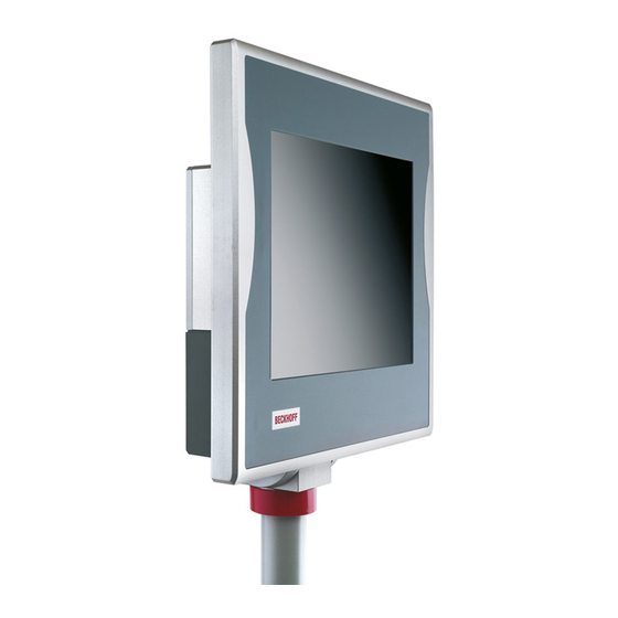
- Page 1 Installation and Operating instructions for “Economy” Panel PC CP72xx Version: 2.1 Date: 2019-10-09...
-
Page 3: Table Of Contents
Installation of the Panel PC Mounting arm installation Earthing measures Power Supply Connection Beckhoff power supply technology Pin assignment of the power supply connector Pre-assembled cable sets for the power supply Fitting the power supply cable with IP65 connector Connecting Power Supply... - Page 4 Shutting down Disposal UPS Software Components (optional) Installation on the PC Help files Troubleshooting Fault correction Beckhoff Support & Service Beckhoff branches and partner companies Beckhoff Headquarters Beckhoff Support Beckhoff Service Appendix Assembly dimensions Dimensions and total weight Appendix Technical data...
-
Page 5: Foreword
All the components are supplied in particular hardware and software configurations appropriate for the application. Modifications to hardware or software configurations other than those described in the documentation are not permitted, and nullify the liability of Beckhoff Automation GmbH & Co. KG. Delivery conditions In addition, the general delivery conditions of the company Beckhoff Automation GmbH &... -
Page 6: Description Of Safety Symbols
Foreword Description of safety symbols The following safety symbols are used in this operating manual. They are intended to alert the reader to the associated safety instructions. Acute risk of injury! If you do not adhere the safety advise adjoining this symbol, there is DANGER immediate danger to life and health of individuals! Risk of injury! -
Page 7: Basic Safety Measures
Foreword Basic safety measures Only switch the PC off after Before the Industrial PC is switched off, software that is running must closing the software be properly closed. Otherwise it is possible that data on the storage medium is lost. Please read the section Switching the Industrial PC on and off. -
Page 8: Operator's Obligation To Exercise Diligence
Foreword Operator’s obligation to exercise diligence The operator must ensure that • the Industrial PC is only used for its intended purpose (see chapter Product Description). • the Industrial PC is only operated in a sound condition and in working order (see chapter Maintenance). •... -
Page 9: Product Description
Appropriate Use The CP72xx Panel PC with 3½” motherboard is designed for mounting behind a Beckhoff Control Panel. Cooling is achieved via heat sink structure between the Control Panel and the add-on PC. A fan inside the closed housing ensures that the heat is distributed evenly. -
Page 10: Access To Memory And Battery
Product Description Access to memory and battery Removing the drive cover After unscrewing the two Allen screws (see arrows) the drive cover can be taken off. View to the hard-disk drive (optional) and the memory card + pole - pole Removing the drive cover allows access to the IDE-hard-disk (1) (optional), the Compact-Flash-memory card (2) and the lithium battery of the system clock (3). - Page 11 Product Description Removing the hard-disk drive and the memory card + pole polarity - pole The hard-disk drive and the memory card can now be pulled out. Here, changing the lithium battery is also possible. The installation takes place in reverse order. Danger of Explosion! Replace battery only with the identical type or an alternative type WARNING...
-
Page 12: Interfaces
Product Description Interfaces Power supply Power supply X101 The power supply connection of the Industrial PC and the connection with the UPS (optional) is established via the power supply socket (X101). Network connection Network connection X106 The Ethernet-interface with RJ-45-connector (X106) allows the PC to be connected to a network (LAN). -
Page 13: Installation Instructions
4. Please keep the associated paperwork. It contains important information for handling the unit. 5. Check the contents for visible shipping damage. 6. If you notice any shipping damage or inconsistencies between the contents and your order, you should notify Beckhoff Service. CP72xx... -
Page 14: Installation Of The Panel Pc
Installation Instructions Installation of the Panel PC The Panel PC series CP72xx is designed for mounting arm installation. A Control Panel is installed in the front of the IP65 Panel PC. The ambient conditions specified for operation must be observed (see the section Technical data). -
Page 15: Earthing Measures
Installation Instructions Mounting arm installation For Installation the Industrial PC at the mounting arm, first push back the red ring cover (1) (see arrows). Now you get access to the allen head screws (2), with which the mounting arm tube is fixed in the adapter. The picture shows the rotatable and tiltable mounting arm adapter (optional). -
Page 16: Power Supply Connection
However, over time this reduces the service life of the battery. The new Beckhoff power supply technology approach addresses this problem and now offers the user the option of switching the PC off without the need for using the battery, thereby reducing the load on the battery. -
Page 17: Pin Assignment Of The Power Supply Connector
Installation Instructions In order to maintain a screen display for the Industrial PC in the event of a power failure, the power supply unit is equipped with a UPS output for connecting a Control Panel. This enables a power failure to be visualised and displayed to the user. -
Page 18: Pre-Assembled Cable Sets For The Power Supply
Installation Instructions Pin assignment CP72x4 with 24-inch display (discontinued) Pin assignment for View connector-sided Wire Function connecting the power Battery Pack (with UPS) supply, the switch and the battery pack (optional) Male ye/gn connector 24 V DC Power Supply PC Unit PC_ON Connector 12-pole Coninvers Power-Status... -
Page 19: Connecting Power Supply
Installation Instructions Connecting Power Supply The external wiring consists of the connection of the power supply, the battery pack (optional) and the connection of customised components for shutting down the PC. Cable Cross Sections Note cable cross sections, For the connection of the power supply, wiring with a cable-cross-section avoid voltage drop! of 1.0 mm must be used. -
Page 20: Wiring Diagram Cp72Xx
Installation Instructions Wiring diagram CP72xx Wiring according to the wiring diagram (the circuit of PC_ON and Power- Status is symbolical): Wiring diagram power supply and external wiring Connection of the Battery Pack Connection of the Battery Pack in combination with integrated UPS (order Note option). -
Page 21: Wiring Diagram Cp72X4 With 24-Inch Display (Discontinued)
Installation Instructions Wiring diagram CP72x4 with 24-inch display (discontinued) Wiring according to the wiring diagram (the circuit of PC_ON and Power- Status is symbolical): Wiring diagram power supply and external wiring Connection of the Battery Pack Connection of the Battery Pack in combination with integrated UPS (order Note option). -
Page 22: Connecting The Network
Installation Instructions Connecting the Network Pre-assembled network cables Pre-assembled network For easy installation of the network connection there are pre-assembled cables connection cables of different length and with IP65 – RJ45 connectors available (see table). In addition to the specified network cables, cables for further configuration are available. -
Page 23: Usb-Interface (Optional)
Installation Instructions USB-interface (optional) Order option C9900-E187 Optionally a USB 2.0 interface with 4-pole-connector (M12-female connector IP65) in the connection area is available with order option C9900-E187: Order number Denomination IP65 connector M12 in the wiring area of a CP72xx for one C9900-E187 USB 2.0 Port Pin assignment for... -
Page 24: Rs232-Interface (Optional)
Installation Instructions RS232-interface (optional) Order option C9900-E186 Optionally a RS232-interface with 12-pole-connector (M12-female connector IP65) is available in the connection area with order option C9900-E186: Order number Denomination IP65-connector M12 in the wiring area of a CP72xx for one C9900-E186 serial interface RS232 Pin assignment for Pin assignment,... -
Page 25: Connecting Devices
Installation Instructions Connecting devices Power supply plug The power supply plug must be withdrawn! Attention Please read the documentation for the external devices prior to connecting them. During thunderstorms, plug connector must neither be inserted nor removed. When disconnecting a plug connector, always handle it at the plug. Do not pull the cable! Connecting cables The connections are located at the top of the Industrial PC and are... -
Page 26: Operating Instructions
Operating Instructions Operating Instructions Please also refer to chapter Foreword. Switching the Industrial PC on and off Switch on The Industrial PC does not have its own mains switch. The Industrial PC will start when the equipment is switched on, or when it is connected to the power supply. -
Page 27: Keyboard Codes
Operating Instructions Keyboard codes Type-dependent number of Depending on the precise type, the Control Panel can have fewer keys keys than those described here. Operation The cursor is the blinking character that marks the point at which the next character entered will be displayed. The cursor is also known as the insertion point. - Page 28 Operating Instructions The meaning of the function keys, F1 to F10, is determined by the software and is displayed at the bottom edge of the display. The function of the special keys above the display is also determined by Einschub Einschub Einschub Einschub...
-
Page 29: Maintenance
Operating Instructions Maintenance Please also refer to chapter Foreword. Cleaning the Industrial PC Disconnect from power supply Switch off the Industrial PC and all connected devices, and disconnect the Industrial PC from the power supply. Attention The Industrial PC can be cleaned with a soft, damp cloth. Do not use any aggressive cleaning materials, thinners, scouring material or hard objects that could cause scratches. -
Page 30: Ups Software Components (Optional)
The driver software comes with a detailed help function. System The help files can be called up either directly from the configuration register by clicking the Help button, or under via Start > Programs > Beckhoff > UPS software components. CP72xx... -
Page 31: Troubleshooting
Nothing happens after the Industrial No power supply to the Industrial Check power supply cable. PC has been switched on Other cause Call Beckhoff Service The Industrial PC does not boot Setup settings are incorrect Check the setup settings fully... -
Page 32: Beckhoff Support & Service
Please contact your Beckhoff branch office or partner company for local support and service on Beckhoff products! The contact addresses for your country can be found in the list of Beckhoff branches and partner companies: www.beckhoff.com You will also find further documentation for Beckhoff components there. -
Page 33: Appendix
Appendix Appendix Assembly dimensions The illustrations show the measurements of the Panel-PCs. Please refer to the tables for the dimensions of the Control Panel. All Dimensions in mm. CP72xx Mounting arm installation from top, rotatable CP72xx... - Page 34 Appendix CP72xx Mounting arm installation from bottom, rotatable CP72xx...
- Page 35 Appendix CP72xx Mounting arm installation from top, rotatable and tiltable CP72xx...
- Page 36 Appendix CP72xx Mounting arm installation from bottom, rotatable and tiltable CP72xx...
-
Page 37: Dimensions And Total Weight
Appendix Dimensions and total weight Display only without Dimensions Weight touch screen CP7201-0000 12“ Display 353.8 326.3 27.5 9.7 kg CP7202-0000 15“ Display 28.5 11.4 kg CP7203-0000 19“ Display 16.3 kg CP7204-00xx 24“ Display 16,0 kg with touch screen Dimensions Weight CP7201-0001 12“... -
Page 38: Appendix
Appendix Appendix Technical data Dimensions and weight See section Assembly dimensions Do not use the PC in areas The Industrial PC may not be used in areas of explosive hazard. of explosive hazard The following conditions must be observed during operation: Environmental conditions Ambient temperature: 0 to 45°C...
Need help?
Do you have a question about the Economy CP72 Series and is the answer not in the manual?
Questions and answers