Beckhoff CP72 Series Installation And Operating Instructions Manual
Hide thumbs
Also See for CP72 Series:
- Installation and operating instructions manual (38 pages) ,
- Manual (48 pages)

Related Manuals for Beckhoff CP72 Series


Summary of Contents for Beckhoff CP72 Series
- Page 1 Installation and Operating instructions for Panel PC CP72xx Version: 1.2 Date: 2007-10-17...
-
Page 3: Table Of Contents
Table of contents Table of contents General Notes Notes on the documentation Liability conditions Description of safety symbols Basic safety measures Operator's obligation to exercise diligence Operator requirements Product Description Appropriate Use Structure Access to memory and battery Interfaces Power supply Network connection Additional plug-in cards (optional) Installation Instructions... - Page 4 Table of contents Troubleshooting Fault correction Service and Support Beckhoff's branch offices and representatives Beckhoff headquarters Beckhoff Support Beckhoff Service Assembly dimensions Dimensions and total weight Appendix Technical data Approvals FCC: Federal Communications Commission Radio Frequency Interference Statement FCC: Canadian Notice...
-
Page 5: General Notes
© This documentation is protected by copyright. Any reproduction or third party use of this publication, whether in whole or in part, without the written permission of Beckhoff Automation GmbH, is forbidden. Description of safety symbols The following safety symbols are used in this operating manual. They are intended to alert the reader to the associated safety instructions. -
Page 6: Basic Safety Measures
General Notes Basic safety measures Only switch the PC off after Before the Industrial PC is switched off, software that is running must closing the software be properly closed. Otherwise it is possible that data on the hard disk is lost. Please read the section Switching the Industrial PC on and off. -
Page 7: Operator's Obligation To Exercise Diligence
General Notes Operator's obligation to exercise diligence The operator must ensure that • the Industrial PC is only used for its intended purpose (see Product Description section); • the Industrial PC is only operated in a sound condition and in working order;... -
Page 8: Product Description
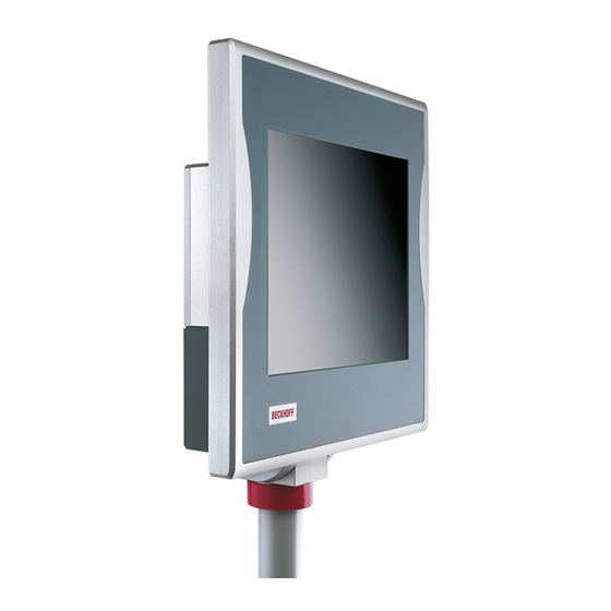
Appropriate Use The CP72xx add-on PC with 3½” motherboard is designed for mounting behind a Beckhoff Control Panel. Cooling is achieved via heat sink structure between the Control Panel and the add-on PC. A fan inside the closed housing ensures that the heat is distributed evenly. -
Page 9: Access To Memory And Battery
Product Description Access to memory and battery Removing the drive cover After unscrewing the two Allen screws (see arrows) the drive cover can be taken off. View to the hard-disk drive (optional) and the memory card Removing the drive cover allows access to the IDE-hard-disk (1) (optional), the Compact-Flash-memory card (2) and the lithium battery of the system clock (3). -
Page 10: Interfaces
Product Description Interfaces Power supply Power supply X101 The power supply connection of the Industrial PC and the connection with the UPS (optional) is established via the power supply socket (X101). Network connection Network connection X106 The Ethernet-interface with RJ-45-connector (X106) allows the PC to be connected to a network (LAN). -
Page 11: Installation Instructions
4. Please keep the associated paperwork. It contains important information for handling the unit. 5. Check the contents for visible shipping damage. 6. If you notice any shipping damage or inconsistencies between the contents and your order, you should notify Beckhoff Service. CP72xx... -
Page 12: Installation Of The Pc
Installation Instructions Installation of the PC The Panel PC series CP72xx is designed for mounting arm installation. A Control Panel is installed in the front of the IP 65 Panel PC. The ambient conditions specified for operation must be observed (see the section Technical data). -
Page 13: Earthing Measures
Installation Instructions Mounting arm installation For Installation the Industrial PC at the mounting arm, first push back the red ring cover (1) (see arrows). Now you get access to the allen head screws (2), with which the mounting arm tube is fixed in the adapter. The picture shows the rotatable and tiltable mounting arm adapter (optional). -
Page 14: Power Supply Connection
Installation Instructions Power Supply Connection Supplied mains power unit The Industrial PC is fitted with a 24 V power supply unit . Optional an uninterruptible power supply (UPS) can be realized using the battery pack C9900-U330. Danger of Explosion if using other battery packs! Danger Connecting Power Supply The external wiring consists of the connection of the power supply, the... -
Page 15: Pin Assignment Of The Power Supply Connector
For connecting the power supply following Coninvers Connector Series RC 12-pole can be used: • Coninvers female connector 12-pole with metric screw connection M16 Crimp Coninvers RM-12S1N8A1100, Beckhoff-No.: 048054 The connector and special tools for the assembly are available via the company Coninvers http://www.coninvers.com as well as different distributors. -
Page 16: Wiring Diagram
Installation Instructions Wiring diagram Wiring according to the wiring diagram (the circuit of PC_ON and Power- Status is symbolical): Wiring diagram power supply and external wiring CP72xx... -
Page 17: Connecting The Network
For network connection following Harting PushPull connector RJ45, 8-pole can be used: • Connector RJ45 8-pole Harting PushPull connector-set according to IEC24702, white No. 09 45 145 1500, Beckhoff-No.: 047177 The connector and special tools for the assembly are available via the company Harting http://www.harting.de/... -
Page 18: Usb-Interface (Optional)
M12 connector IP 65, screw type, 4 pin, second end USB-B connector Fitting the USB-cable with IP 65 connector Required connector For connecting the USB-interface the following connector is needed cable- sided: • Connector 4-pole round shield Binder 99142981404, Beckhoff-No. 050536 For further information see http://www.binder-connector.de/. CP72xx... -
Page 19: Rs232-Interface (Optional)
D-Sub 9 pin plug Fitting the RS232-interface cable with IP 65 connector Required connector For connecting the RS232-interface the following connector is needed cable-sided: • Cable with connector M12 12-pole, 12x0,14mm² 5m Escha 8028494 , Beckhoff-No.: 050541 For further information see http://www.escha.de/. CP72xx... -
Page 20: Connecting Devices
Installation Instructions Connecting devices The Panel-PC must never be connected or disconnected in an area that is subject to explosion hazard! Risk of explosion! Danger The power supply plug must be withdrawn! Warning Please read the documentation for the external devices prior to connecting them. -
Page 21: Operating Instructions
Operating Instructions Operating Instructions Please also refer to chapter General Notes. Switching the Industrial PC on and off Switch on The Industrial PC does not have its own mains switch. The Industrial PC will start when the equipment is switched on, or when it is connected to the power supply. -
Page 22: Servicing And Maintenance
Operating Instructions Servicing and maintenance Please also refer to chapter General Notes. Cleaning the Industrial PC Switch off the Industrial PC and all connected devices, and disconnect the Industrial PC from the power supply. Danger The Industrial PC can be cleaned with a soft, damp cloth. Do not use any aggressive cleaning materials, thinners, scouring material or hard objects that could cause scratches. -
Page 23: Ups Software Components (Optional)
The driver software comes with a detailed help function. System The help files can be called up either directly from the configuration register by clicking the Help button, or under via Start > Programs > Beckhoff > UPS software components. CP72xx... -
Page 24: Troubleshooting
Nothing happens after the Industrial No power supply to the Industrial Check power supply cable. PC has been switched on Other cause. Call Beckhoff Service. The Industrial PC does not boot Setup settings are incorrect. Check the setup settings. fully Other cause. -
Page 25: Service And Support
Fax: +49(0)5246/963-198 e-mail: info@beckhoff.com Beckhoff Support Support offers you comprehensive technical assistance, helping you no only with the application of individual Beckhoff products, but also with other, wide-ranging services: • world-wide support • design, programming and commissioning of complex automation systems •... -
Page 26: Assembly Dimensions
Assembly dimensions Assembly dimensions The illustrations show the measurements of the Panel-PCs. Please refer to the tables for the dimensions of the Control Panel. All Dimensions in mm. CP72xx Mounting arm installation from top, rotatable CP72xx... - Page 27 Assembly dimensions CP72xx Mounting arm installation from bottom, rotatable CP72xx...
- Page 28 Assembly dimensions CP72xx Mounting arm installation from top, rotatable and tiltable CP72xx...
- Page 29 Assembly dimensions CP72xx Mounting arm installation from bottom, rotatable and tiltable CP72xx...
-
Page 30: Dimensions And Total Weight
Assembly dimensions Dimensions and total weight Display only without Dimensions Weight touch screen CP7201-0000 12“ Display 353.8 326.3 27.5 9.7 kg CP7202-0000 15“ Display 28.5 11.4 kg CP7203-0000 19“ Display 16.3 kg with touch screen Dimensions Weight CP7201-0001 12“ Display 353.8 326.3 27.5... -
Page 31: Appendix
Appendix Appendix Technical data Dimensions and weight See section Assembly dimensions Do not use the PC in areas The Industrial PC may not be used in areas of explosive hazard. of explosive hazard The following conditions must be observed during operation: Environmental conditions Ambient temperature: 0 to 45°C...
Need help?
Do you have a question about the CP72 Series and is the answer not in the manual?
Questions and answers