Table of Contents

Related Manuals for Inficon AP29ECO


Summary of Contents for Inficon AP29ECO
- Page 1 Original operating instructions AP29ECO Sampling Probe for Sentrac Desktop and Sentrac Panel Catalog No. 590-035 (3 cc/sec sample flow), 590-036 (1 cc/sec sample flow) ninb69en1-02-(2401) From software version 4.01 or higher...
- Page 2 INFICON AB Wahlbecksgatan 25A SE-582 13 Linköping Sweden...
-
Page 3: Table Of Contents
4.1 Placement of Sample Probe ........................ 17 4.2 Cable Connections.......................... 18 4.2.1 Sensor Cable .......................... 18 4.2.2 Bus Cable ........................... 19 4.3 Pneumatic Connections for AP29ECO .................... 20 4.3.1 Sample Inlet .......................... 21 4.3.2 Calibration Gas ........................... 22 4.3.3 Pressure regulator ........................ 22 4.3.4 Reference Air .......................... - Page 4 Table of Contents INFICON 4.4.3 Programmable Logic Controller with Sentrac External DSUB IO Adapter........ 26 4.5 Test area .............................. 27 4.5.1 Tracer gas supply ........................ 27 4.5.2 Pressure regulator ........................ 27 4.5.3 Tracer gas exhaust ........................ 28 4.5.4 Fresh air............................ 28 5 Operation ..............................
- Page 5 INFICON Table of Contents 11.1.8 Electrical ratings.......................... 45 11.1.9 Electromagnetic Compatibility..................... 46 11.2 Sniffer Flow Options.......................... 46 11.2.1 Standard flow .......................... 46 11.2.2 Optional flow 1 .......................... 46 AP29ECO_Operating-instructions-ninb69en1-02-(2401)
-
Page 6: Introduction
The Sampling Probe AP29ECO forms together with the Hydrogen Leak Detector Sensistor Sentrac Panel a complete industrial leak-detection unit. Sampling probe AP29ECO is intended for intermittent or continuous sampling of a test point or test chamber. It performs quick and accurate accept/reject testing. - Page 7 INFICON Introduction | 1 WARNING Pure Hydrogen is a flammable gas. Use only ready-made mixtures of 5% Hydrogen in Nitrogen. This is a standard, industrial gas mixture used in various industrial applications. Whenever the word Hydrogen is used throughout this manual it implies that hydrogen gas is safely mixed with Nitrogen in proportions 5% H –...
-
Page 8: System Description
Sensistor Sentrac software. Consult your supplier for best system design for your particular application. The AP29ECO is equipped with one sniffer port that has one constant flow with two functions. One flow (Samplings flow) does not measure the hydrogen concentration while the other (Measuring flow) does. -
Page 9: Connect Tracer Gas Filler
System Description | 2 2.1 Connect Tracer Gas filler INFICON offers a range of products that can be combined for making up most of your entire test system. The design work can therefore, often be kept to an absolute minimum. -
Page 10: Test Sequence
2 | System Description INFICON 2.3 Test Sequence There are four major steps in the test sequence. (Timers are set in the Sensistor Sentrac): 1. Accumulation 2. Sampling 3. Measuring 4. Purging See figure 2 below Fig. 2: Test sequence 10 / 48... -
Page 11: Accumulating Time (Settings / Probe / Apc 1)
2.3.2 Sampling Time (Settings / Probe / APC 1) This is the time needed to draw a sample from the test point to the AP29ECO. If sampling time is too short, the sample will not reach the sensor. An excessively long sample time may pump away the sample in a small open chamber. -
Page 12: Other Important Software Parameters
2 | System Description INFICON 2.3.6 Other important software parameters • Reject Level (Settings / Measure Mode / Setup) Gas signals above the Reject Level result in REJECT. Gas signals below the Reject Level result in ACCEPT. • Calibration Value (Settings / Calibration / Setup 1) Calibrate against a Calibration gas you should set Calibration Value equal to the concentration of Hydrogen in your calibration gas. -
Page 13: Quick Start
Connect Sentrac External DSUB IO Adapter to I/O (APC) port on the Sensistor Sentrac backside. Connect Buscable to the Sentrac External DSUB IO Adapter and AP29ECO D- sub port. Connect one Probe Cable C21 from Sentrac (front or rear) Probe Connection to Combox60 Detector port. -
Page 14: Setup Settings
3 | Quick Start INFICON 3.2 Setup Settings Open Settings / Probe / Functions and set probe Type to AP29ECO. Open Settings / Probe / APC 1 and if necessary, optimize timers for shortest cycle time. 14 / 48 AP29ECO_Operating-instructions-ninb69en1-02-(2401) -
Page 15: Measuring
Press ð Abort Measuring ð Go to Standby ð Purge the sample hose more 3.4 Remote Control AP29ECO Go to set up remote control instead of controlling from Sentrac display read: Manual switches [} 25] Programmable Logic Controller etc. [} 25] AP29ECO_Operating-instructions-ninb69en1-02-(2401) -
Page 16: Installation
Installation of the AP29ECO is very simple, follow the instructions below. The APC system of the Sensistor Sentrac handles all vital functions. The AP29ECO can also be controlled through the APC Bus via switches, sensors and indicators, or via a PLC/PC. -
Page 17: Placement Of Sample Probe
The probe can be installed in any position. We recommend that the AP29ECO is placed with the ventilation grid facing down. This makes it harder for dirt or dust to collect inside the box. -
Page 18: Cable Connections
INFICON 4.2 Cable Connections 4.2.1 Sensor Cable The sensor inside the AP29ECO is connected to the Sensistor Sentrac with two C21 cables and one COMBOX60. Several different cable lengths are available. See sensor cable in the figure below. Fig. 4: Sensor cable Align the red mark on the cable contact with the red mark on the panel contact and push straight in. -
Page 19: Bus Cable
The APC Bus is a simple discrete I/O bus. Each digital input and output has its own pin/wire on the bus. See Table 1 below for description of which pins are used for controlling the AP29ECO. Further details of the APC System can be found below and in the Sensistor Sentrac Interface Description. -
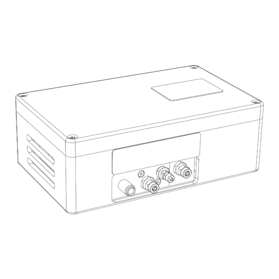
Page 20: Pneumatic Connections For Ap29Eco
4 | Installation INFICON 4.3 Pneumatic Connections for AP29ECO The figure 5 shows the pneumatic connections of AP29ECO. Exhaust Reference air Sample Inlet Calibrating gas Fig. 5: Pneumatic connections of the AP29ECO See table below for more information about the pneumatic connections. -
Page 21: Sample Inlet
• Make sure that the position of the sample inlet is as close as possible to the primary leak point. The main application for the AP29ECO is leak testing. By placing the inlet close to the main leak point you minimize the risk that a malfunction in the test system will result in leaking objects being passed as not leaking. -
Page 22: Calibration Gas
4 | Installation INFICON 4.3.2 Calibration Gas The calibration gas is used to calibrate the hydrogen sensor. Gas sensors are inherently different from physical sensors in that they are less “stable”. The sensitivity changes over time. You will need to calibrate your sensor much more often, typically every day for best accuracy. -
Page 23: Reference Air
INFICON Installation | 4 Recommended specification: Two-stage regulator. Output pressure range: 0 – 0.10 MPa / 0 – 1 barg / 0 – 15 psig. 4.3.4 Reference Air The reference air is your signal background. The hydrogen content in your samples will be compared with the reference air. -
Page 24: Master Controls
The AP29ECO can also be controlled by manual switches or by a supervising computer such as a programmable logic controller. This section describes the different signals used for controlling and interpreting the test. -
Page 25: Manual Switches
Table 2: Functions operated manually 4.4.2 Programmable Logic Controller etc. The AP29ECO is designed to be controlled by any standard PLC using 24 VDC logic. The detectors have 24 VDC transistor outputs capable of delivering 0.5 A each (max 2.5 A together). - Page 26 4 | Installation INFICON Status Output/ Description Function Pin Designation Pin Designation Input AP29ECO Sentrac DET_ON HIGH when detector power is on. Reject REJECT. Test result signal Accept ACCEPT. Test result signal DET_ERROR Summing error from detector or probe DET_WAIT...
-
Page 27: Test Area
Tracer gas testing proves an object to be leak free if no gas is found. Therefore it is essential that the filling of tracer gas is carried out correctly and that all relevant parameters are properly controlled and supervised. We strongly recommend the use of one of INFICON’s tracer gas controllers. 4.5.2 Pressure regulator WARNING Pure Hydrogen is a flammable gas. -
Page 28: Tracer Gas Exhaust
4 | Installation INFICON The best way of avoiding this kind of problem is to buy a good two-stage regulator. They do not exhibit such pressure dependence. 4.5.3 Tracer gas exhaust Tracer gas exhaust should be transported directly out of the building. The exhaust should be placed on the roof of the building far away from the fresh air intake. - Page 29 INFICON Installation | 4 • Combustion engines. Vehicles inside and outside of your building can produce large amounts of hydrogen. It is common that such exhaust gases are carried into the general ventilation system. Do not take fresh air from ventilation system.
- Page 30 4 | Installation INFICON Fig. 7: Principle of air curtain design 30 / 48 AP29ECO_Operating-instructions-ninb69en1-02-(2401)
-
Page 31: Operation
INFICON Operation | 5 5 Operation 5.1 Measure Sequence Flow Chart The measure sequence is shown in the figure below. Start Accumulation Sampling > Purge level? Set REJECT output Measuring Leak? Purging Set REJECT output Purging Set ACCEPT output Purging To Standby Fig. 8: Measure sequence flow chart... -
Page 32: Measure Sequence Signals
5 | Operation INFICON 5.2 Measure Sequence Signals Measure sequence signals are shown in the table below. See under “Installation” for pin numbers. Signal name Description IN_5 Give pulse (high ≥ 40 ms) to initiate measuring ACCEPT High after completed test cycle showing no leak Goes low again 10 s after purging time has run out. -
Page 33: Setting Up Your Application
INFICON Operation | 5 5.5 Setting up your Application This section will list the more important of the software parameters of the Sensistor Sentrac system. It is our intention that this section will guide you when adjusting the test parameters to suit your specific application. Note that every application is unique and that you need a deeper understanding of the behavior of the tracer gas mix to get the most of your leak detection equipment. - Page 34 This is the Timer under the APC Settings menu. This is the time needed to draw a sample from the test point into the AP29ECO. If sampling time is too short, the sample will not reach the sensor. An excessively long sample time may pump away the sample in a small open chamber.
- Page 35 5. After test purging time This is the Timer under the APC Settings menu. You can set the AP29ECO to purge the sample hose with air inwards after each completed test. The Timer sets the purge time. Set the timer initially to 0 seconds.
-
Page 36: Preventive Maintenance
INFICON 6 Preventive Maintenance The AP29ECO has been designed for a minimum of maintenance. The best way to keep maintenance at a minimum is to fit external fine grade filters on reference air and sample inlets. Recommended filter grade is 40 µm or finer. -
Page 37: Cleaning Port Filters
INFICON Preventive Maintenance | 6 If you know that your environment is dirty or dusty, we recommend that an external filter be fitted to the sample hose. Chose a filter grade of 10-40 um, in a filter cartridge with small internal volume. Excess filter volumes can add many seconds and even minutes to the sampling time. -
Page 38: Membrane Pump
6 | Preventive Maintenance INFICON Fig. 10: Calibration Gas Port Connector Filter disc O-ring Orifice disc Clean filter as follows: 1. Switch off system power. 2. Shut off all gas and air supplies. 3. Remove hose from connector (1). 4. Remove connector (1) from valve manifold. -
Page 39: Replacing Gas Sensor
INFICON Preventive Maintenance | 6 6.5 Replacing Gas Sensor The status of the sensor is automatically checked at every calibration. The detector will indicate when the sensor needs to be replaced. Replace the sensor when this message is shown at calibration: “Sensitivity too low for Reject level”... - Page 40 6 | Preventive Maintenance INFICON 8. Connect sensor cable. Make sure it has locked by pulling gently on the cable. 9. Switch on detector again. 10. Calibrate the new sensor! 40 / 48 AP29ECO_Operating-instructions-ninb69en1-02-(2401)
-
Page 41: Trouble Shooting
INFICON Trouble Shooting | 7 7 Trouble Shooting Symptom / Message Cause Remedy "Sample flow error" or Sample inlet filter is Clean or replace filter. "Measure flow error" clogged. Sample pump (-M02) is Clean or replace pump. clogged or damaged. -
Page 42: Spare Parts
8 | Spare Parts INFICON 8 Spare Parts Description INFICON order number Gas sensor 590-250 Sensor cable 590-161 Bus cable 591-282 Sentrac External DSUB IO Adapter 598-330 Port filter disk (10 µm) 591-173 Port filter O-ring ( 5.1 x 1.6 mm) -
Page 43: Electric Diagram
INFICON Electric Diagram | 9 9 Electric Diagram AP29ECO_Operating-instructions-ninb69en1-02-(2401) 43 / 48... -
Page 44: Pneumatic Diagram
10 | Pneumatic Diagram INFICON 10 Pneumatic Diagram 44 / 48 AP29ECO_Operating-instructions-ninb69en1-02-(2401) -
Page 45: Technical Data
INFICON Technical Data | 11 11 Technical Data 11.1 General 11.1.1 Sensitivity • Concentration: Same as detector. • Using 5% H2 tracer gas: 0.5 ppm or 3x10⁻⁵ atm cc/s for direct sniffing with standard sniffer flow 11.1.2 Sniffer flow alarm Set to 75% of nominal flow. - Page 46 11 | Technical Data INFICON 11.1.9 Electromagnetic Compatibility ISO4414:1998, JIS B 8370 11.2 Sniffer Flow Options 11.2.1 Standard flow 3 atm. cc/s with std 0.16 mm orifice. 11.2.2 Optional flow 1 1 atm. cc/s with 0.10 mm orifice. 46 / 48...
Need help?
Do you have a question about the AP29ECO and is the answer not in the manual?
Questions and answers