Table of Contents
Advertisement
Quick Links
PCIe-DIO13
User Manual
Version 0.3
ⓒ 2005 DAQ SYSTEM Co., Ltd. All rights reserved.
Microsoft® is a registered trademark; Windows®, Windows NT®, Windows XP®, Windows 7®, Windows 8®, Windows 10®
All other trademarks or intellectual property mentioned herein belongs to their respective owners.
Information furnished by DAQ SYSTEM is believed to be accurate and reliable, However, no responsibility is assumed by DAQ SYSTEM for its use, nor
for any infringements of patents or other rights of third parties which may result from its use. No license is granted by implication or otherwise under
any patent or copyrights of DAQ SYSTEM.
The information in this document is subject to change without notice and no part of this document may be copied or reproduced without the prior
written consent.
Advertisement
Table of Contents

Subscribe to Our Youtube Channel
Related Manuals for DAQ system PCIe-DIO13


Summary of Contents for DAQ system PCIe-DIO13
- Page 1 All other trademarks or intellectual property mentioned herein belongs to their respective owners. Information furnished by DAQ SYSTEM is believed to be accurate and reliable, However, no responsibility is assumed by DAQ SYSTEM for its use, nor for any infringements of patents or other rights of third parties which may result from its use. No license is granted by implication or otherwise under any patent or copyrights of DAQ SYSTEM.
-
Page 2: Table Of Contents
1. Introduction 1-1 Product Features --------------------------------------------------------------------- 2. PCIe-DIO13 Function 2-1 Board Block Diagram ------------------------------------------------------------------------ 2-2 Camera Link Cable and Connector --------------------------------------------------------- 2-3 Camera Link and PCIe-DIO13 --------------------------------------------------------------- 3. PCIe-DIO13 Board Description 3-1 Board Layout ------------------------------------------------------------------------ Device Features ---------------------------------------------------------------------- 4. Installation... -
Page 3: Introduction
PCIe-DIO13 User’s Manual 1. Introduction The PCIe-DIO13 is a Data Transfer Interface Board to save external FIFO memory. With based PCI Express x1, it supports a LVDS high speed Data Transfer through the Direct Memory Access(DMA). According to the Camera Link Interface Standard for a Digital Camera and Frame Grabber, a MDR 26- pin connector for Camera Link (Camera Link) cable is used. -
Page 4: Pcie-Dio13 Function
2. PCIe-DIO13 Function 2-1 Board Block Diagram The PCIe-DIO13 internal function of the configuration is shown in Figure 2-1. The PC interface access the board local bus by the PCI bus standard through the exchange transform “PCI Express – PCI Translator”. DMA, data output, output control, is performed on the FPGA, and is controlled by the API command from PC, the state monitoring. -
Page 5: Camera Link Cable And Connector
PCIe-DIO13 User’s Manual 2-2 Camera Link Cable and Connector The connection between the camera link cameras and PCIe-DIO13 board uses the 26 Pin MDR cable. The Camera Link cable consists of twin-axial shielded cable and 2 Mini MDR 26-male plug. -
Page 6: Camera Link And Pcie-Dio13
The receiving device (module) that receives data from PCIe-DIO13 must receive the signal replaced by the Frame Grabber Connector pin map of Base Configuration according to the cross connection of the camera link cable. For example, the PCIe-DIO13 connector pin 2 (DO_0-) is connected to the receiving device connector pin 25. - Page 7 PCIe-DIO13 User’s Manual [Table 1. MDR-26 Connector(J1)] Pin No. Name Description Remark Inner Shield Cable shield DO_0- Data Out 0- DO_1- Data Out 1- DO_2- Data Out 2- ENABLE- Write Enable Out- DO_3- Data Out 3- PAUSE+ Data Transfer Pause In+...
-
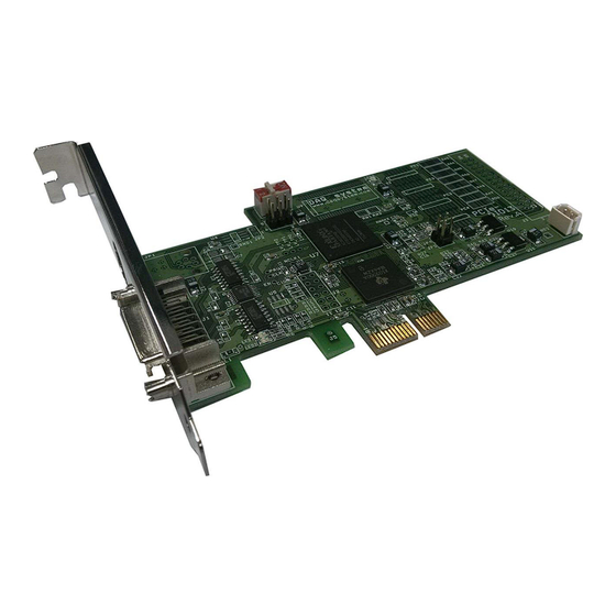
Page 8: Pcie-Dio13 Board Description
PCIe-DIO13 User’s Manual 3. PCIe-DIO13 Board Description In this chapter, the primary functions of the PCIe-DIO13 board are described briefly. For more information, refer to the device specification. 3-1 Board Layout LVDS FPGA Transciver PCI Express LVDS -PCI Regulators Ext. -
Page 9: Device Features
PCIe-DIO13 User’s Manual 3-2 Device Features (1) LVDS Transceiver LVDS Input, Output Signal Transceiver (2) LVDS Transmitter LVDS Output Signal Transmitter (3) SW1 Board Selection Switch (4) FPGA All of the board functions are controlled by the Logic program. (5) PCI Express-PCI Translator... -
Page 10: Installation
Therefore you can install it easily. Your OS requirements are Windows 2000 SP4 or Windows XP SP1 above, Windows 7. The PCIe-dio13 connects to Express Card Port. After that you can show the below picture of “New Hardware Search Wizard” window. - Page 11 PCIe-DIO13 User’s Manual Click “Next” after selecting the PCIe-DIO13 board Driver in CD. In the middle of the installation, "Windows XP Compatibility" Check to inquire about, click the Continue button.
- Page 12 PCIe-DIO13 User’s Manual The installation process proceeds is as follows. If the installation is completely finished, Click “Finish”.
- Page 13 [My Computer -> properties -> Hardware -> Device Manager -> Multifunction Adaptors -> PCI-DIO13] If you can see the “PCIe-DIO13” at Multifunction Adaptors, the driver installation is to have been over. (Check the red circle) Important Notice : After installation, you should re-boot the system for the proper...
-
Page 14: Sample Program
PCIe-DIO13 User’s Manual 5. Sample Program DAQ system provides a sample program to make the user be familiar with the board operation and to make the program development easier. You can find the sample program in the CDROM accompanying with the board. - Page 15 PCIe-DIO13 User’s Manual To run the sample application program, you need to use API, it is a form of client DLL. To compile the sample source to make its executable file, you have to use Import Library files and header files.
-
Page 16: Appendix
PCIe-DIO13 User’s Manual Appendix A-1 Board Size The external dimensions of the board are as follows. 120.8... -
Page 17: Repair Regulations
(3) All DAQ SYSTEM products have a one-year warranty. -. The warranty period is counted from the date the product is shipped from DAQ SYSTEM. -. Peripherals and third-party products not manufactured by DAQ SYSTEM are covered by the manufacturer's warranty. - Page 18 1. Specification of Camera Link Interface Standard for Digital Cameras and Frame Grabbers -- Camera Link committee 2. PCI Local Bus Specification Revision2.1 -- PCI Special Interest Group 3. AN201 How to build application using API -- DAQ system 4. AN312 PCIe-DIO13 API Programming -- DAQ system...
- Page 19 PCIe-DIO13 User’s Manual MEMO Contact Point Web sit : https://www.daqsystem.com Email : postmaster@daqsystem.com...
Need help?
Do you have a question about the PCIe-DIO13 and is the answer not in the manual?
Questions and answers