Table of Contents
Advertisement
Quick Links
PCIe-HDMI01
User Manual
Version 1.0
ⓒ 2005 DAQ SYSTEM Co., Ltd. All rights reserved.
Microsoft® is a registered trademark; Windows®, Windows NT®, Windows XP®, Windows 7®, Windows 8®, Windows 10®
All other trademarks or intellectual property mentioned herein belongs to their respective owners.
Information furnished by DAQ SYSTEM is believed to be accurate and reliable, However, no responsibility is assumed by DAQ SYSTEM for its use, nor
for any infringements of patents or other rights of third parties which may result from its use. No license is granted by implication or otherwise under
any patent or copyrights of DAQ SYSTEM.
The information in this document is subject to change without notice and no part of this document may be copied or reproduced without the prior
written consent.
Advertisement
Table of Contents

Related Manuals for DAQ system PCIe-HDMI01


Summary of Contents for DAQ system PCIe-HDMI01
- Page 1 All other trademarks or intellectual property mentioned herein belongs to their respective owners. Information furnished by DAQ SYSTEM is believed to be accurate and reliable, However, no responsibility is assumed by DAQ SYSTEM for its use, nor for any infringements of patents or other rights of third parties which may result from its use. No license is granted by implication or otherwise under any patent or copyrights of DAQ SYSTEM.
-
Page 2: Table Of Contents
PCIE-HDMI01 User’s Manual Contents 1. Introduction -------------------------------------------------------------------------- 1-1 Product Features ------------------------------------------------------------------------- 1-2 Product Application ------------------------------------------------------------------------- 2. PCIe-HDMI01 Board Function 2-1 PCIe-HDMI01 Board Layout -------------------------------------------------------------- 2-2 Connector Pin out 2-2-1 HDMI Connector --------------------------------------------------------------------- 2-2-2 J3 Connector -------------------------------------------------------------------- 2-2-3 J5 Connector --------------------------------------------------------------------... -
Page 3: Introduction
[Figure 1-1. PCIe-HDMI01 Board Usage] [Figure 1-1] shows an example of using the PCIe-HDMI01 board by connecting the board to the PCI Express slot of the right PC. Screens of various devices on the left can be transmitted to the... -
Page 4: Product Features
PCIE-HDMI01 User’s Manual 1-1 Product Features Items Description Remark Hardware PC Interface PCI Express 4x Operation Power PCI Express 12V Video Interface High-Definition Multimedia 2 Channel (Two ports support HDMI ( optional 1 channel use) Interface) 3GHz Receiver Display Resolution... -
Page 5: Product Application
PCIE-HDMI01 User’s Manual 1-2 Product Applications Image recognition (Pattern, particle, etc.) Inspection equipment (Sensor, Semiconductor, Device etc.) Security Solution Medical Image Capture BLU-RAY Game Console... -
Page 6: Pcie-Hdmi01 Board Function
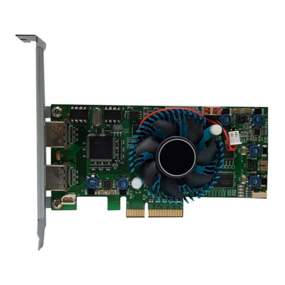
PCIE-HDMI01 User’s Manual 2. PCIe-HDMI01 Board Function 2-1 PCIe-HDMI01 Board Layout Port A www.daqsystem.com Port B PCIe-HDMI01 REV. A PCI Express 4x Interface [Figure 2-1. PCIe-HDMI01 Layout] There are several LEDs on the board, and the description of each is as follows. -
Page 7: Connector Pin Out
PCIE-HDMI01 User’s Manual Connector Pin MAp 2-2-1 HDMI Connector : J1(Port A), J2(Port B) The connector is an HDMI signal connector and the pin map is as shown below. [Figure 2-2. HDMI pin-out] [Table 1. HDMI 커넥터 J1, J2] Pin No... -
Page 8: J3 Connector
It is an external input 12V power connector. 2-2-3 J5 Connector PCIE-HDMI01 board is designed to use up to 4 PCIe-DHMI01 boards simultaneously in one system (PC). Each board classification can be set through the 4-pin DIP switch in the board. -
Page 9: Installation
PCIE-HDMI01 User’s Manual 3. Installation Before installing the board, check that the contents of the package are intact. 3-1. Hardware Installation 3-1-1 Product Contents ① PCIe-HDMI01 Board ② CD (Driver/Manual/API/Sample Source etc.) Document Folder : Manual and Catalog Driver Folder : pci_hdmi01.sys pci-hdmi01.inf... -
Page 10: Driver Installation
The board environment should be used in Windows 2000 SP4 or higher and Windows XP SP1 or higher. First, power off the PC, plug the PCIe-HDMI01 board into the PCI Express Slot, and turn on the PC. When the “Start New Hardware Search Wizard” window opens as shown below, select it as shown below and click the Next button. - Page 11 PCIE-HDMI01 User’s Manual 2. Select the Driver folder that is suitable for O.S (32/64bit) and click the Next button. 3. Click the Next button. Check if the driver is installed normally.
- Page 12 5. If it appears as shown in the picture below, the installation has been completed normally. The picture above shows the screen where the PCIe-HDMI01 board is normally installed in the PC. Note: After initial installation, you must reboot your PC for normal operation.
-
Page 13: Sample Program
PCIE-HDMI01 User’s Manual 4. Sample Program A sample program is provided on the CDROM provided with the board so that the board can be used easily. In order to test the sample program, the driver of the board must be installed first. The sample program is provided in the form of a source so that the API provided to use the board can be briefly tested, so users can modify and use it. - Page 14 PCIE-HDMI01 User’s Manual The program execution sequence to view the image is as follows. ① “Open” click ② Select from PORT A/B ③ After click Set Resolution / RGB or YUV Out / Bit Set. I.C Set click ④ “Dev. Init” click ⑤...
- Page 15 PCIE-HDMI01 User’s Manual (10) “Read” button The image frame saved on the board is read to the PC (Hexa value). If the image frame is not saved on the board, you have to wait until the saving is complete. Use after freeze the screen.
- Page 16 PCIE-HDMI01 User’s Manual (14) “Compare” selection When selected, the original file and the saved file are compared, and the Compare folder is created and saved in the execution folder. (\Release\Compare\Original.bin) (15) “Error to Save” selection When Compare is selected, error files are saved in \Release\Compare\\Err%d.bin in the wrong byte order.
-
Page 17: Appendix
PCIE-HDMI01 User’s Manual Appendix Board Size The external sizes of the board are as follows. For detailed dimensions, please contact the person in charge. -
Page 18: Repair Regulations
PCIE-HDMI01 User’s Manual A-2 Repair Regulations Thank you for purchasing a DAQSYSTEM product. Please refer to the following regarding Customer Service regulated by DAQSYSTEM. (1) Read the user manual and follow the instructions before using the DAQSYSTEM product. (2) When returning the product to be repaired, please write down the symptoms of the failure and send it to the head office. - Page 19 PCIE-HDMI01 User’s Manual MEMO Contact Point Web sit : https://www.daqsystem.com Email : postmaster@daqsystem.com...
Need help?
Do you have a question about the PCIe-HDMI01 and is the answer not in the manual?
Questions and answers