Advertisement
Quick Links
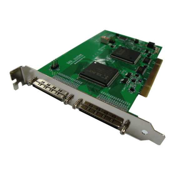
PCI-DIO02
Windows, Windows2000, Windows NT and Windows XP are trademarks of Microsoft. We acknowledge that the
trademarks or service names of all other organizations mentioned in this document as their own property.
Information furnished by DAQ system is believed to be accurate and reliable. However, no responsibility is assumed by DAQ
system for its use, nor for any infringements of patents or other rights of third parties which may result from its use. No license is
granted by implication or otherwise under any patent or copyrights of DAQ system.
The information in this document is subject to change without notice and no part of this document may be copied or
reproduced without the prior written consent.
User's Manual
Copyrights 2007 DAQ system, All rights reserved.
1-
-
PCI-DIO02 Users Manual (Rev 1.0)
http://www.daqsystem.com
Advertisement

Subscribe to Our Youtube Channel
Related Manuals for DAQ system PCI-DIO02


Summary of Contents for DAQ system PCI-DIO02
- Page 1 Information furnished by DAQ system is believed to be accurate and reliable. However, no responsibility is assumed by DAQ system for its use, nor for any infringements of patents or other rights of third parties which may result from its use. No license is granted by implication or otherwise under any patent or copyrights of DAQ system.
-
Page 2: Table Of Contents
PCI-DIO02 Users Manual (Rev 1.0) Contents 1. PCI-DIO02 Block Diagram 2. PCI-DIO02 Internal Placement 3. Connector Pin Map & SW1 Setup 3.1 Front Panel – CN1 (MDR 100pin) 3.2 Box Header – J1 3.3 Address Setup – SW1 3.4 I/O Register Map 4. -
Page 3: Pci-Dio02 Block Diagram
1. PCI-DIO02 Block Diagram [Figure 1-1. PCI-DIO02 Internal Block Diagram] The PCI-DIO02 is designed high speed digital logger with PCI interface. It composed of 128bit I/O ports for external interface like a Figure 1-1. (Usable a selection Input/Output at programs) It is possibility selective Read/Write to 16bit each 8 groups. -
Page 4: Pci-Dio02 Internal Placement
PCI-DIO02 Users Manual (Rev 1.0) 2. PCI-DIO02 Internal Placements [Figure 2-1. PCI-DIO02 Placement] Name Description and Note VHDCI68 connector / External interface (I/O 64~127) VHDCI68 connector / External interface (I/O 0~63) Board Number Setup Switch Serial Flash program EPLD I/O Expansion EPLD System control FPGA http://www.daqsystem.com... -
Page 5: Connector Pin Map & Sw1 Setup
PCI-DIO02 Users Manual (Rev 1.0) 3. Connector Pin Map & SW1 Setup 3.1 VHDCI68 – J1 [Figure 3-1. J1 Pin Map] 3.2 VHDCI68 – J2 [Figure 3-2. J2 Pin Map] The PCI-DIO02 is used to 2 VHDCI68 connector for external I/O interface. http://www.daqsystem.com... -
Page 6: Address Setup - Sw1
PCI-DIO02 Users Manual (Rev 1.0) 3.3 Address Setup – SW1 Several DIO02 series boards classify each board address, you shall use it at systems that a lot of I/O ports was required. Distribution of each board sets it up through 4 pin switch (SW1) in a board. A system is designed of 4 maximum boards at the same time so as usable. -
Page 7: Installation
2. CD (Driver/Manual/API/Sample Source etc.) 4.2 Installation Sequence To install your PCI-DIO02 board in your PC, follow the steps described in the document “How to install PCI DAQ Board” provided by DAQ System. If the document is missing, you can get it from www.daqsystem.com. - Page 8 PCI-DIO02 Users Manual (Rev 1.0) For installation of the driver, you need a “pci_di02.inf” and “pci_dio02.sys” files at driver folder. http://www.daqsystem.com...
- Page 9 PCI-DIO02 Users Manual (Rev 1.0) “Finish” button click. If the installation is completely finished, you confirm it in the following ways. Do the following steps to show up the “Device Manager” window. [My Computer -> Properties -> Hardware -> Device Manager ->...
- Page 10 PCI-DIO02 Users Manual (Rev 1.0) http://www.daqsystem.com...
- Page 11 PCI-DIO02 Users Manual (Rev 1.0) If you can see the “PCI-DIO02” at the Multi-functions Adaptors, the driver installation is to have been over. (Check the red circle) Important Notice : After installation, you should re-boot the system for the proper operation.
-
Page 12: Application Program Explanation
PCI-DIO02 Users Manual (Rev 1.0) 5. Application Program Explanation DAQ system provides a sample program to make the user be familiar with the board operation and to make the program development easier. You can find the sample program in the CDROM accompanying with the board. - Page 13 PCI-DIO02 Users Manual (Rev 1.0) Name Description Note Model No Select the Model Name PCI-DIO02 selection Board No Select the Board Number By SW1 Setup Open Device Open the selected Board List Device It displays a board number which installed in a Not Used currently.
- Page 14 PCI-DIO02 Users Manual (Rev 1.0) References 1. PCI System Architecture -- MindShare Inc. 2. PCI Local Bus Specification -- PCI-SIG 3. General information on PCI board API -- DAQ system 4. AN201 How to build application using APIs -- DAQ system 5.
Need help?
Do you have a question about the PCI-DIO02 and is the answer not in the manual?
Questions and answers