Table of Contents
Advertisement
Quick Links
PCIe-OPT01
Windows, Windows2000, Windows NT and Windows XP are trademarks of Microsoft. We acknowledge that the
trademarks or service names of all other organizations mentioned in this document as their own property.
Information furnished by DAQ system is believed to be accurate and reliable. However, no responsibility is assumed by DAQ
system for its use, nor for any infringements of patents or other rights of third parties which may result from its use. No license is
granted by implication or otherwise under any patent or copyrights of DAQ system.
The information in this document is subject to change without notice and no part of this document may be copied or
reproduced without the prior written consent.
User's Manual
Copyrights 2019 DAQ system, All rights reserved.
1-
-
PCIe-OPT01 Users Manual (Rev 1.0)
http://www.daqsystem.com
Advertisement
Table of Contents

Subscribe to Our Youtube Channel
Related Manuals for DAQ system PCIe-OPT01


Summary of Contents for DAQ system PCIe-OPT01
- Page 1 Information furnished by DAQ system is believed to be accurate and reliable. However, no responsibility is assumed by DAQ system for its use, nor for any infringements of patents or other rights of third parties which may result from its use. No license is granted by implication or otherwise under any patent or copyrights of DAQ system.
-
Page 2: Table Of Contents
PCIe-OPT01 Users Manual (Rev 1.0) -- Contents – 1. Introduction 2. PCIe-OPT01 Function 2.1 PCIe-OPT01 Board Description 2.2 SFP(Small Form Factor Pluggable) 2.3 Main Connector Pin-out 2.3.1 J3 Connector 2.3.2 J4 Switch 2.3.3 J8 Connector 2.3.4 J10 Connector 3. Installation 3.1 Hardware Installation... -
Page 3: Introduction
PCIe-OPT01 Users Manual (Rev 1.0) 1. Introduction PCIe-OPT01 board is used with MIPI-OPT06, which is a MIPI C-PHY/D-PHY receiving board, or MIPI-OPT08 board that receives MIPI D-PHY/Parallel signals, and receives optical-transmission data from the board and transmits it to the host PC It is a light receiving board. Images are acquired in real time and transferred directly to the system memory. - Page 4 PCIe-OPT01 Users Manual (Rev 1.0) [Figure 1-1] shows the connection between PCIe-OPT01 and MIPI-OPT06 board that receives C-PHY or D-PHY signal of MIPI sensor. It is a board that transmits signals received through optical transmission to a PC through the PCI Express 4x interface method. The operation of the board is controlled by the program API.
-
Page 5: Pcie-Opt01 Function
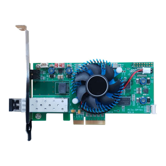
PCIe-OPT01 Users Manual (Rev 1.0) 2. PCIe-OPT01 Function 2.1 PCIe-OPT01 Board Description system www.daqsystem.com PCIe-OPT01 Rev. D PCI Express 4x Interface [Figure 2-1. PCIe-OPT01 Layout] (1) SFP (CN1) : SFP(Small Form Factor Pluggable) Cage. (2) FPGA (U3) : All functions of the board are controlled through this FPGA Logic. -
Page 6: Sfp(Small Form Factor Pluggable)
PCIe-OPT01 Users Manual (Rev 1.0) 2.2 SFP(Small Form Factor Pluggable) In the case of PCIe-OPT01, SFP is used as a Fiber-Transmission Transceiver. The SFP transceiver is designed to support various optical transmissions such as SONET, Gigabit Ethernet, and Fiber Channel. It supports hot-pluggable transceiver and can be connected to network device motherboard with fiber or copper networking cable. - Page 7 PCIe-OPT01 Users Manual (Rev 1.0) Tx Rate Select Open or Low = 2.125 or 4.25 Gb/s Fibre Channel (Low Bandwidth) High = 8.5 Gb/s Fibre Channel (High Bandwidth) VeeR Receiver Ground Receiver Ground VeeR Receiver Data Receiver Inverted Data VeeR...
-
Page 8: Main Connector Pin-Out
Express PCI power 12V can be connected to the external connector (J10). 2.3.2 J4 Switch The PCIe-OPT01 board is designed to use up to 4 PCIe-OPT01 boards simultaneously in one system (PC). Classification of each board can be set through the 4-pin DIP switch (J4) in the board. -
Page 9: Installation
PCIe-OPT01 Users Manual (Rev 1.0) 3. Installation Before installing the board, check whether the contents of the package are abnormal. 3.1 Hardware Installation 3.1.1 Product Contents ① PCIe-OPT01 Board ② CD (Driver/Manual/API/Sample Source etc.) 3.1.2 Installation Process ① Turn off the computer. - Page 10 The board environment should be used in Windows 2000 SP4 or higher and Windows XP SP1 or higher. First, power off the PC, plug the PCIe-OPT01 board into the PCI Express Slot, and turn on the PC. When the “Start New Hardware Search Wizard” window opens as shown below, select it as shown below and click the Next button.
- Page 11 PCIe-OPT01 Users Manual (Rev 1.0) 2. Select Driver from the enclosed CD and click the Next button. 3. Click the Next button. It indicates that the installation process is in progress as shown below. http://www.daqsystem.com...
- Page 12 4. Click the Next button. 5. When the installation is complete, check whether the driver is installed normally in the following way. 6. In My Computer -> Properties -> Hardware -> Device Manager, check whether the multifunctional adapter -> “PCIe-OPT01” is installed. http://www.daqsystem.com...
- Page 13 7. If it appears as shown in the figure below, the installation was successful. The picture above shows the screen where the PCIe-OPT01 board is normally installed in the PC. Note: After initial installation, it is recommended to reboot the PC for normal operation.
-
Page 14: Sample Program
PCIe-OPT01 Users Manual (Rev 1.0) 4. Sample Program A sample program “FrameTest.exe” is provided in the Exe folder of the CDROM provided with the board so that the board can be easily used. Frame Data is displayed as a hexadecimal value so that it can be stored in memory or hard disk so that the frame data needed by developers can be used, and it is an executable file that shows the screen as a video for easy user to understand. -
Page 15: Board Related Function
PCIe-OPT01 Users Manual (Rev 1.0) ormally, there must be API DLL (mipi_iot.dll), or it must be in the Windows system folder or t he folder designated by the Path environment variable. The description of each menu bar is as follows. Menu bars not described here are functi ons that are not used. -
Page 16: Image Frame Related Function
PCIe-OPT01 Users Manual (Rev 1.0) DDR Use : DDR memory is used. D Phy : When selected, D-Phy is set as the LVDS input mode. The default setting is C-PHY. Alt pwr : 108M : 108M sensor is used. Cable : When selected, LVDS input mode is set to cable connection. The default setting is direct connection. - Page 17 PCIe-OPT01 Users Manual (Rev 1.0) 0x30B1 0x00 0x30C7 0x00 0x3115 0x0E 0x3118 0x42 0x311D 0x34 0x3121 0x0D 0x3212 0xF2 0x3213 0x0F ……………. 0x3306 0x12 0x3307 0x03 0x3308 0x0D 0x3309 0x05 0x330A 0x09 0x330B 0x04 0x330C 0x08 0x330D 0x05 0x330E 0x03...
- Page 18 PCIe-OPT01 Users Manual (Rev 1.0) (7) “RGGB;BGGR;GRBG;BGGR” : Choose from Bayer Mode (8) “Get Res.” button It shows the image resolution. (9) “Once” button Press the Toggle button to show the screen once. (10) “Data” button The image frame saved on the board is read into PC (Hexa value). If the image frame is not saved on the board, you have to wait until the saving is complete.
-
Page 19: Clock Related Function
PCIe-OPT01 Users Manual (Rev 1.0) (16) “Read ID” button Shows MIPI ID. 4.3 Clock related functions (1) “PGM Clk” toggle Select the corresponding Sensor Clock. (2) “Set” button It is set according to the frequency set next to Sensor Clock. In the above case, it is set to 10MHz. -
Page 20: Power/Digital/Io Related Function
PCIe-OPT01 Users Manual (Rev 1.0) 4.4 Power/Digital/IO related functions (1) “Set VIO” button Set by specifying the sensor voltage value. (0 ~ 3.3V) (2) Digital I/O(USER;Sensor;User3.3V;PWR) : Selection (Power Board Connection Standard) PCI_DIO_XXXX : User GPIO (General Purpose I/O) MIPI-OPT06/08 Refer to board... -
Page 21: I2C Related Function
PCIe-OPT01 Users Manual (Rev 1.0) 4.5 I2C related functions (1) “Init” button Initialize the I2C registers. (2) “Write” Button Send data through I2C. (3) “Read” Button Reads the data of the address of the selected mode among SYS, PWR, ADC, and OS modes below. -
Page 22: Auto Test Related Function
PCIe-OPT01 Users Manual (Rev 1.0) “ADC” : AD Converter “OS” : Open Short 4.6 Auto Test related functions (1) “RUN” toggle: Test the board as a whole. “Test Period”: You can set the test period in seconds. “Stop on Err”: Stop error output. -
Page 23: Spi Related Function
PCIe-OPT01 Users Manual (Rev 1.0) 4.7 SPI related functions ”Get DMA Size” Button: Gets the DMA Buffer size. ”Set DMA Size” Button: Set the DMA buffer size. ”PCI ddr Reset” Button: Initializes the DDR memory. 4.8 OS SPI related functions “OS SPI Send”... -
Page 24: Misc Related Function
PCIe-OPT01 Users Manual (Rev 1.0) 4.9 MISC related functions Various types of conditions can be selected and used. “+5V Power”: Outputs VIO power. ”I/O Power”: Turns on/off the power of external signals used for MIPI. “Sensor I2C Off”: Turns Sensor I2C operation On/Off. -
Page 25: Status Related Function
PCIe-OPT01 Users Manual (Rev 1.0) 4.10 STATUS related functions It shows the number of the following 4 error states that occur during image transmission. “OV”: Overflow “UR”: UnRead “SE”: SizeError “SI”: Size “CRC Check”: Activates the LVDS Check Sum function. -
Page 26: Appendix
PCIe-OPT01 Users Manual (Rev 1.0) Appendix A.1 General Specification Specification General Supports 2Channel Fiber Link PCI Express Gen2 x4 interface Support a Full Camera Link Interface One SFP(Small Form Factor Pluggable) C onnectors with full support ... - Page 27 PCIe-OPT01 Users Manual (Rev 1.0) A.2 Board Size The external dimensions of the board are as follows. (132 x 68 mm) http://www.daqsystem.com...
- Page 28 PCIe-OPT01 Users Manual (Rev 1.0) References 1. PCI Local Bus Specification Revision2.1 -- PCI Special Interest Group 2. How to install PCI DAQ Board -- DAQ system 3. AN201 How to build application using API -- DAQ system 4. AN312 PCIe-OPT01 API Programming -- DAQ system http://www.daqsystem.com...
Need help?
Do you have a question about the PCIe-OPT01 and is the answer not in the manual?
Questions and answers