Table of Contents
Advertisement
Quick Links
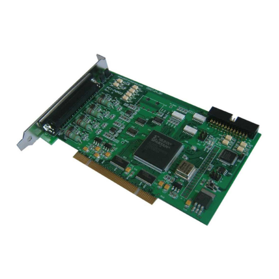
PCI-PWM02
Windows, Windows2000, Windows NT and Windows XP are trademarks of Microsoft. We acknowledge that the
trademarks or service names of all other organizations mentioned in this document as their own property.
Information furnished by DAQ system is believed to be accurate and reliable. However, no responsibility is assumed by DAQ
system for its use, nor for any infringements of patents or other rights of third parties which may result from its use. No license is
granted by implication or otherwise under any patent or copyrights of DAQ system.
The information in this document is subject to change without notice and no part of this document may be copied or
reproduced without the prior written consent.
User's Manual
Copyrights 2005 DAQ system, All rights reserved.
1-
-
PCI-PWM02 Users Manual (Rev 1.4)
http://www.daqsystem.com
Advertisement
Table of Contents

Related Manuals for DAQ system PCI-PWM02


Summary of Contents for DAQ system PCI-PWM02
- Page 1 Information furnished by DAQ system is believed to be accurate and reliable. However, no responsibility is assumed by DAQ system for its use, nor for any infringements of patents or other rights of third parties which may result from its use. No license is granted by implication or otherwise under any patent or copyrights of DAQ system.
-
Page 2: Table Of Contents
PCI-PWM02 Users Manual (Rev 1.4) Contents 1. Block Diagram 2. Connecter Pin Map 2-1. Dsub-37Pin Panel 2-2. Multi Board Setup 3. Circuit Connection 3-1. PWM Output 3-2. Trigger Input 3-3. Digital Output 3-4. Digital Input 4. External Connection 4-1. External Power 4-2. -
Page 3: Block Diagram
PCI-PWM02 Users Manual (Rev 1.4) 1. PCI-PWM02 Block Diagram In the case of PCI-PWM02, as shown in [Figure 1-1], four digital PWM (Pulse Width Modulation) control blocks are configured to interface with the outside. PWM is widely used to control the speed control of DC motor and adjust the light quantity of lighting products such as LED by controlling the average voltage by changing the duty ratio within a certain period. - Page 4 PCI-PWM02 Users Manual (Rev 1.4) SPECIFICATION ▣ PWM Output ▪ Number of Channels : 4 ▪ Number of Trigger Input : 4 ▪ Resolution : 1us ▪ Timer : 22bit ▪ Output Level : 12V(External) ▣ Isolated Digital Input ▪ Number of Channels : 6 ▪...
- Page 5 PCI-PWM02 Users Manual (Rev 1.4) SOFTWARE ▣ Operating system ▪ Windows 2000/XP/Windows 7 ▣ Recommended Software ▪ Visual basic/C++ with Board API(DLL) http://www.daqsystem.com...
-
Page 6: Connecter Pin Map
PWM3 OUT PWM2 +12V PWM2 OUT PWM1 +12V PWM1 OUT PWM0 +12V PWM0 OUT [Figure 2-1. PCI-PWM02 Connecter Pin] [Table 1. PCI-PWM02 37 pin Description] Pin# Name Description Remark PWM0 OUT PWM Channel 0 Output PWM1 OUT PWM Channel 1 Output... - Page 7 PCI-PWM02 Users Manual (Rev 1.4) EXT +12V External Power +12V Input PWM0 TRG PWM Channel 0 Trigger Input PWM2 TRG PWM Channel 2 Trigger Input TRG_COM Trigger Input Common DIN1 Digital input 1 Input DIN3 Digital input 3 Input DIN5...
-
Page 8: Multi Board Setup
PCI-PWM02 Users Manual (Rev 1.4) 2-2. Multi Board Setup If mounting works in one system that a lot of I/O ports are required, the PCI-PWM02 boards are classified according to each board address. Distribution of each board sets it up through 4 pin switch (JP3). -
Page 9: Circuit Connection
PCI-PWM02 Users Manual (Rev 1.4) 3. Circuit Connection 3-1. PWM Output Circuit LED Module + terminal PWMx +12V - terminal PWMx OUT [Figure 3-1. PWM Output Connection Circuit] Figure 3-1 shows that the PWM output connects to the LED modules. It is used to connect the +12V of PWM0-4 to the LED module “+”, PWM0-4 OUT to LED module “–”... - Page 10 PCI-PWM02 Users Manual (Rev 1.4) 3-2. Trigger Input Circuit TRG_COM Trigger0 4.7K PWM0 TRG Trigger3 4.7K PWM3 TRG [Figure 3-2. Trigger Input Circuit] Figure 3-2 shows that each PWM output get from trigger input if it let operate in trigger mode.
- Page 11 PCI-PWM02 Users Manual (Rev 1.4) 3-3. Digital Output Circuit DOUT0_C Dout0 DOUT11_C Dout11 DOUT_COM [Figure 3-3. Isolated Digital Output Circuit] Figure 3-3 shows that each digital output makes output as isolated photo-coupler. Each output gets from over-current protection by resistance of 22 ohms, it use a common output terminal.
- Page 12 PCI-PWM02 Users Manual (Rev 1.4) 3-4. Digital Input Circuit DIN_COM Input0 4.7K DIN0 Input5 4.7K DIN5 [Figure 3-4. Isolated Digital Input Circuit] Figure 3-4 shows that each digital input is isolated by photo-coupler, input has a common input terminal and each input terminal. The resistor of 4.7K ohms is connected in a series, each input can get from 12 and 24V.
-
Page 13: External Connection
PCI-PWM02 Users Manual (Rev 1.4) 4. External Connection 4-1. In case of external power use In case of External Power Use EXT +12V EXT +12V DC +12V [Figure 4-1. External Connection (External Power Use)] If +12V of PC power is lack of acting a LED module, it shall use external power. In case of using external power connection Figure 4-1 shows. - Page 14 PCI-PWM02 Users Manual (Rev 1.4) 4-2. In case of internal power use In case of Internal Power Use [Figure 4-2. Internal Power Use] In case of using internal PC power (+12) use, connection shall work 1-2 jumper (J1) like Figure 4-2.
-
Page 15: Trigger Motion Mode
PCI-PWM02 Users Manual (Rev 1.4) 5. Trigger Motion mode Trigger Input PWM Output Output Delay Output Term [Figure 5-1. Trigger Mode Motion] Figure 5-1 shows trigger motion mode to control PWM output by external trigger. It can be set up output delay and output time in trigger mode, setting is possible until the maximum 4,194,303usec in each 1usec until in time as use a 22bit timer. -
Page 16: Installation
To install your PCI-PWM02 board in your PC, follow the steps described in the document “How to install PCI DAQ Board” provided by DAQ System. If the document is missing, you can get it from www.daqsystem.com. The PCI-PWM02 board is completely Plug & Play. There are no switches or jumpers to set. - Page 17 PCI-PWM02 Users Manual (Rev 1.4) The driver folder includes a file of “pci_pwm02.inf” and “pci_pwm02.sys” that it is necessary for driver installation. A warning message appears during installation here, press “Continue Anyway” button. You can show below message window. The process progress as follows.
- Page 18 PCI-PWM02 Users Manual (Rev 1.4) If the installation is completely finished, you can show below message window. http://www.daqsystem.com...
- Page 19 “Device Manager” window. [My Computer -> properties -> Hardware -> Device Manager -> Multifunction Adaptors -> PCI-PWM02] If you can see the “PCI-PWM02”, the driver installation is to have been over. (Check the red circle) Notice : After installation, you should re-boot the system for the proper operation.
-
Page 20: Sample Program
PCI-PWM02 Users Manual (Rev 1.4) 7. Sample Program DAQ system provides a sample program to make the user be familiar with the board operation and to make the program development easier. You can find the sample program in the CDROM accompanying with the board. - Page 21 PCI-PWM02 Users Manual (Rev 1.4) [Figure 7-2. When Sample program “PCI_PWM02_MULTI.exe‟ is executed] To run the sample application program, you need to use API, it is a form of client DLL. To compile the sample source to make its executable file, you have to use Import Library files and header files.
- Page 22 PCI-PWM02 Users Manual (Rev 1.4) 7-1. PWM0 ~ PWM03 Function (1) Pulse width „Read‟ Button Read current setup PWM value. (2) Pulse width „Write‟ Button Control each PWM output. The setup value range is 0 ~ 255. One time variation of the set value is 25 ns.
- Page 23 Read current setup Digital input. The digital input have 6 inputs. 7-4. System Function (1) „Get # of Board‟ Button Confirm the how many PCI-PWM02 board install in the PC. (2) Select Board Select the board number. (0 ~3) http://www.daqsystem.com...
- Page 24 PCI-PWM02 Users Manual (Rev 1.4) (3) „Exit‟ Button Close the device of all PCI-PWM02. 7-5. Auto Display (PWM0) Function The operation of automatically increasing or decreasing the output operation of PWM0 is repeated. 'PWM Auto' Check: The initial value is added to the increment value, and the current value is output.
- Page 25 PCI-PWM02 Users Manual (Rev 1.4) References 1. PCI System Architecture -- MindShare Inc. 2. PCI Local Bus Specification -- PCI-SIG 3. General information on PCI board API -- DAQ system 4. AN201 How to build application using APIs -- DAQ system 5.
Need help?
Do you have a question about the PCI-PWM02 and is the answer not in the manual?
Questions and answers