Table of Contents
Advertisement
Quick Links
PCIe-AIO15
Windows, Windows2000, Windows NT and Windows XP are trademarks of Microsoft. We acknowledge that the
trademarks or service names of all other organizations mentioned in this document as their own property.
Information furnished by DAQ system is believed to be accurate and reliable. However, no responsibility is assumed by DAQ
system for its use, nor for any infringements of patents or other rights of third parties which may result from its use. No license is
granted by implication or otherwise under any patent or copyrights of DAQ system.
The information in this document is subject to change without notice and no part of this document may be copied or
reproduced without the prior written consent.
User's Manual
Copyrights 2010 DAQ system, All rights reserved.
1-
-
PCIe-AIO15 Users Manual (Rev 1.0)
http://www.daqsystem.com
Advertisement
Table of Contents

Related Manuals for DAQ system PCIe-AIO15


Summary of Contents for DAQ system PCIe-AIO15
- Page 1 Information furnished by DAQ system is believed to be accurate and reliable. However, no responsibility is assumed by DAQ system for its use, nor for any infringements of patents or other rights of third parties which may result from its use. No license is granted by implication or otherwise under any patent or copyrights of DAQ system.
-
Page 2: Table Of Contents
PCIe-AIO15 Users Manual (Rev 1.0) CONTENTS Introduction PCIe-AIO15 Internal Block PCIe-AIO05 Board Description 3.1 Outline 3.2 Main Device Functions 3.3 Connectors and Switches 3.3.1 D-Sub25 Connecter: J12 3.3.2 D-Sub9 Connecter: J3 3.3.3 Analog Input Amplification Setup 3.3.4 Board Address Setup (SW5) 3.3.5 Analog Input Mode Selection... - Page 3 PCIe-AIO15 Users Manual (Rev 1.0) Conversion Time Setup Installation 7.1 Hardware Installation 7.1.1 Product Contents 7.1.2 Installation Process 7.2 Driver Installation Sample Program 8.1 System Function 8.2 ADC (Analogue Digital Converter) Test Function 8.3 ADC Graph related function description 8.4 DIO related function description References http://www.daqsystem.com...
-
Page 4: Introduction
PCIe-AIO15 Users Manual (Rev 1.0) 1. Introduction The PCIe-AIO15 is an analog input, digital input / output PCI Express (x1) board that supports 16- to 24-bit analog to digital converter (ADC) 4 channels and digital I / O 4 channels. All of the board's controls are designed as Field Programmable Gate Arrays (FPGAs), so they can be freely changed or supplemented and easily upgraded to meet your needs. -
Page 5: Pcie-Aio15 Internal Block
ADC 4ch 16/24bit Resolution [Figure 2-1. PCIe-AIO15 Internal Block Diagram] The PCIe-AIO15 is a board having the multi functions of Input/Output PCI board with the 16/24-bit ADC 4 channels and 4-bit DIO function.. GENERAL DESCRIPTION ♦ Multi-function Data acquisition board ♦... - Page 6 PCIe-AIO15 Users Manual (Rev 1.0) APPLICATION ♦ PCI development and evaluation ♦ Data acquisition ♦ Laboratory instrumentation ♦ Process control systems ♦ Factory automation SPECIFICATION ▣ Analog input ▪ 16~24bit resolution ▪ 4 Single ended or 2 Differential Input ▪ 0 to +5V, 0 to 10V, ±5. ±10V Software-Programmable input range ▣...
-
Page 7: Pcie-Aio05 Board Description
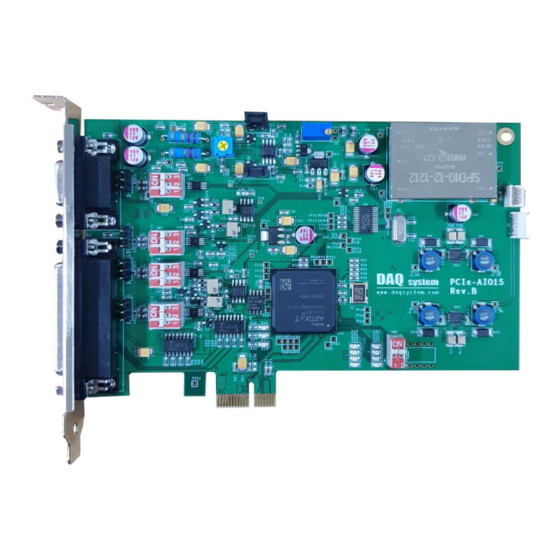
PCIe-AIO15 Users Manual (Rev 1.0) 3. PCIe-AIO15 Board Description The PCIe-AIO15 board's features, connector and pin assignments, and software (API) are compatible with the PCI-AIO05 and can be replaced. Brief descriptions of each important board function are provided. 3.1 Outline [Figure 3-1. -
Page 8: Main Device Functions
PCIe-AIO15 Users Manual (Rev 1.0) 3.2 Main Device Function (1) D-Sub 9 Pin : J3 Analog Input 1 Channel, Digital Input/Output 1 Channel, Reference Power (2) D-Sub 25 Pin : J12 Analog Input 3 Channel, Digital Input/Output 3 Channel, Reference Power (3) FPGA : U15 All board functions are controlled through this FPGA logic. - Page 9 PCIe-AIO15 Users Manual (Rev 1.0) 3.3 Main Device Function The D-SUB 9pin and 25pin connector which was fixed to standard PCI Bracket is used for Analog and Digital signal Input/Output. [Figure 3-2. PCIe-AIO15 PCI Bracket] http://www.daqsystem.com...
- Page 10 PCIe-AIO15 Users Manual (Rev 1.0) 3.3.1 D-sub25 Connector : J12 REF+ REF- AIN1+ AIN1- A+10V AGND REF+ REF- AIN2+ AIN2- A+10V AGND REF+ REF- AIN3+ AIN3- A+10V AGND EOUT3 EOUT2 EOUT1 EIN3 EIN2 EIN1 DGND [Figure 3-3. PCIe-AIO15 D-sub25 Connecter Pin] http://www.daqsystem.com...
- Page 11 PCIe-AIO15 Users Manual (Rev 1.0) [Table 1. PCIe-AIO15 D-sub 25 Pin Connecter Description] Pin# Pin Name Description Remark DGND Digital Ground Ground EIN2 Digital Input Channel 2 EOUT1 Digital Output Channel 1 Open-Collector EOUT3 Digital Output Channel 3 Open-Collector A+10V...
-
Page 12: D-Sub9 Connecter: J3
DGND +12VPCI AIN0- EOUT0 AIN0+ EIN0 REF- AGND REF+ [Figure 3-4. PCIe-AIO15 D-sub9 Connecter Pin] [Table 2. PCIe-AIO15 D-sub 9 Pin Connecter Description] Pin# Pin Name Description Remark REF+ Load Cell Reference Power +5V Output REF- Load Cell Reference Power... -
Page 13: Analog Input Amplification Setup
PCIe-AIO15 Users Manual (Rev 1.0) 3.3.3 Analog Input Amplification Setup An input signal is amplified by Op-amp. The AIN0~AIN3 signal is selected the amplification by DIP switch SW1~SW4. Signal Amplification SW1 ~ SW4 OFF OFF x100.0 x199.4 x298.4 OFF OFF x399.4... -
Page 14: Analog Input Mode Selection
PCIe-AIO15 Users Manual (Rev 1.0) 3.3.5 Analog Input Mode Selection An Input signal is possible to use Differential (Balance, DI) and Single-ended (Unbalance, SE) input. According to AIN0~AIN3 signals, the input type select by switch J2, J7, J9, J11 setup. -
Page 15: Analog Input Connection
PCIe-AIO15 Users Manual (Rev 1.0) 4. Analog Input Connection 4-1. Unbalance Input J2, J7, J9, J11 Jumper Setup ADC CH0-3 Sensor [Figure 4-1. Analog SE (Single Ended) Input Connection] An analog SE connection connects a signal to a Positive port, a ground to a Negative port. And, a J1~J4 connecter of board connects like Figure 4-1. -
Page 16: Digital Input/Output Feature
PCIe-AIO15 Users Manual (Rev 1.0) 5. Digital Input/Output Featues 5.1 Input +3.3V +12VPCI 4.7K EIN0 DIN0 +3.3V 4.7K DIN3 EIN3 [Figure 5-1. Digital Input] External Digital Input Signals (EINx) get a isolated logic signal as separated with Photo- Transistor like Figure 5-1. -
Page 17: Conversion Time Setup
PCIe-AIO15 Users Manual (Rev 1.0) 6. Conversion Time Setup Inside AD Converter have a digital filter. The filter characteristic by filter word (FW) is different. Have a good noise characteristic and effective bit that had better use a lot of FW, but time to get outside data is required very much. -
Page 18: Installation
Tighten the screws on the board's bracket and case to secure the bracket. ⑤ In case of multi board, start again from step 3. Connect the PCIe-AIO15 board to an empty PCI Express slot on your PC. After powering on, the Found New Hardware window will appear. - Page 19 PCIe-AIO15 Users Manual (Rev 1.0) 7.2 Installation Sequence To install your PCIe-AIO15 board in your PC, follow the steps described in the document “How to install PCI DAQ Board” provided by DAQ System. If the document is missing, you can get it from www.daqsystem.com.
-
Page 20: Driver Installation
PCIe-AIO15 Users Manual (Rev 1.0) The driver folder includes a file of “pci_aio05.inf” and “pci_aio05.sys” that it is necessary for driver installation. A warning message appears during installation here, press “Continue Anyway” button. You can show below message window. The process progress as follows. - Page 21 PCIe-AIO15 Users Manual (Rev 1.0) If the installation is completely finished, you can show below message window. http://www.daqsystem.com...
- Page 22 PCIe-AIO15 Users Manual (Rev 1.0) If the installation is completely finished, you confirm it in the following ways. Do the following steps to show up the “Device Manager” window. [My Computer -> properties -> Hardware -> Device Manager -> Multifunction Adaptors -> PCI-AIO15] If you can see the “PCI-AIO15”...
-
Page 23: Sample Program
PCIe-AIO15 Users Manual (Rev 1.0) 8. Sample Program DAQ system provides a sample program to make the user be familiar with the board operation and to make the program development easier. You can find the sample program in the CDROM accompanying with the board. -
Page 24: System Function
PCIe-AIO15 Users Manual (Rev 1.0) To run the sample application program, you need to use API, it is a form of client DLL. To compile the sample source to make its executable file, you have to use Import Library files and header files. - Page 25 Conversion time set up. (Refer to Table 3) (5) Select Channel Write the ADC channels. The PCIE-AIO15 channel numbers are from 0 to 3. (6) Select Range Set up the ADC input range per channel. (0 to 5, ±5, 0 to 10V, ±10V)) (7) Average Numbers It designate the data number that a moving average is applied to 0 ~ 255.
- Page 26 PCIe-AIO15 Users Manual (Rev 1.0) 8.3 ADC Graph (1) Offset It is an offset to display graph. As an offset value is added to data collection, it is used if data aren‟t marked to a graph. (2) Divide It is a division value to display graph.
- Page 27 PCIe-AIO15 Users Manual (Rev 1.0) 8.4 DIO Function (1) DIO Auto Read Automatic read DIO value. (2) „DIO Read‟ Button Press this button to read the data on General Purpose I/O port. Reading Data are recorded the editor box beside the button (3) „DIO Write‟...
- Page 28 PCIe-AIO15 Users Manual (Rev 1.0) References 1. PCI System Architecture -- MindShare Inc. 2. PCI Local Bus Specification -- PCI-SIG 3. General information on PCI board API -- DAQ system 4. AN201 How to build application using APIs -- DAQ system 5.
Need help?
Do you have a question about the PCIe-AIO15 and is the answer not in the manual?
Questions and answers