Table of Contents
Advertisement
Quick Links
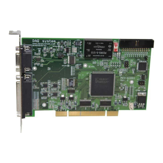
PCI-AIO01
Windows, Windows2000, Windows NT and Windows XP are trademarks of Microsoft. We acknowledge that the
trademarks or service names of all other organizations mentioned in this document as their own property.
Information furnished by DAQ system is believed to be accurate and reliable. However, no responsibility is assumed by DAQ
system for its use, nor for any infringements of patents or other rights of third parties which may result from its use. No license is
granted by implication or otherwise under any patent or copyrights of DAQ system.
The information in this document is subject to change without notice and no part of this document may be copied or
reproduced without the prior written consent.
User's Manual
Copyrights 2009 DAQ system, All rights reserved.
1-
-
PCI-AIO01 Users Manual (Rev 1.0)
http://www.daqsystem.com
Advertisement
Table of Contents

Subscribe to Our Youtube Channel
Related Manuals for DAQ system PCI-AIO01


Summary of Contents for DAQ system PCI-AIO01
- Page 1 Information furnished by DAQ system is believed to be accurate and reliable. However, no responsibility is assumed by DAQ system for its use, nor for any infringements of patents or other rights of third parties which may result from its use. No license is granted by implication or otherwise under any patent or copyrights of DAQ system.
-
Page 2: Table Of Contents
PCI-AIO01 Users Manual (Rev 1.0) Contents PCI-AIO01 Block Diagram Connector Pin Map Board Address Setup Analog Output Connection Diagram Analog Input Connection Diagram Installation 6.1 Package content 6.2 Installation Sequence Sample Program 7.1 System Function 7.2 ADC Test Function 7.3 DAC Test Function 7.4 Select Channel graph... - Page 3 PCI-AIO01 Users Manual (Rev 1.0) UPDATE HISTORY 2010-10-12 API Function Add ADC_StartBufferedRead() ADC_StoptBufferedRead() ADC_GetBufferedData() ADC_GetBufferedDataEx() ADC_SetAvgCounter() API Function Supplement ADC_GetData() 2010-11-05 (Rev 0.9) API Function Add GetBoardVersion() - It will apply to Board Version2. 2011-07-04 (Rev1.0) 6. Installation Add 7. Sample Program Add...
-
Page 4: Pci-Aio01 Block Diagram
12/14/16-bit Resolution [Figure 1-1. PCI-AIO01 Internal Block Diagram] The PCI-AIO01 is a board having the functions of analog I/O PCI board with the 12-bit DAC 2 channels, 12/14/16-bit ADC 8 channels. Support a 32-bit, 33MHz 5/3.3V PCI Bus 8-Ch Input 12/14/16-bit ADC(8-CH SE or 4-Ch DI Support) Support various ADC Input Range (+5V, +10V, ±5V, ±10V) -
Page 5: Connector Pin Map
PCI-AIO01 Users Manual (Rev 1.0) 2. Connector Pin Map The D-SUB 9pin and 25pin connector which was fixed to standard PCI Bracket is used for Analog signal Input/Output. [Figure 2-1. PCI-AIO01 PCI Bracket] http://www.daqsystem.com... - Page 6 PCI-AIO01 Users Manual (Rev 1.0) DGND TRG_OUT1 FACE_IN1 TRG_IN1 TRG_OUT0 FACE_IN0 TRG_IN0 AGND REF25 ADC IN7 ADC IN6 ADC IN5 ADC IN4 ADC IN3 ADC IN2 ADC IN1 ADC IN0 [Figure 2-2. PCI-AIO01 D-sub25 Connector Pin] http://www.daqsystem.com...
- Page 7 PCI-AIO01 Users Manual (Rev 1.0) [Table 1. PCI-AIO01 D-sub 25 Pin Connector Description] Pin# Pin Name Description Remark ADC IN0 Analog Input Channel 0 +/- 10V Input ADC IN2 Analog Input Channel 2 +/- 10V Input ADC IN4 Analog Input Channel 4...
- Page 8 PCI-AIO01 Users Manual (Rev 1.0) DAC GROUND DAC SYNC DAC CH1 DAC CH0 [Figure 2-3. PCI-AIO01 D-sub9 Connector Pin] [Table 2. PCI-AIO01 D-sub 9 Pin Connector Description] Pin# Pin Name Description Remark DAC CH0 Analog Output Channel 0 +/- 10V Output...
-
Page 9: Board Address Setup
PCI-AIO01 Users Manual (Rev 1.0) 3. Board Address Setup If mounting works in one system that a lot of I/O ports are required, several AIO series boards are classified according to each board address. Distribution of each board sets it up through 4 pin DIP switch (SW1). A system is designed of maximum four boards at the same time so as usable. -
Page 10: Analog Output Connection Diagram
PCI-AIO01 Users Manual (Rev 1.0) 4. Analog Output Connection Diagram DAC CH0/1 DAC GROUND Actuator [Figure 4-1. Analog Output Connection Diagram] An analog output goes out through D-sub 9 pin connector like Figure 4-1. The two analog channel outputs are making it with bases of channel0, channel 1 by DAC Ground. Always output channel and DAC GROUND shall be connected outside with pairs. -
Page 11: Analog Input Connection Diagram
PCI-AIO01 Users Manual (Rev 1.0) 5. Analog Input Connection Diagram ADC CH0-7 AGND Sensor [Figure 5-1. Analog SE (Single Ended) Input Connection] A common analog GROUND(AGND) works input basis for the SE connection. At this time, the input channel has total 8 channels. -
Page 12: Installation
2. CD (Driver/Manual/API/Sample Source etc.) 6.2 Installation Sequence To install your PCI-AIO01 board in your PC, follow the steps described in the document “How to install PCI DAQ Board” provided by DAQ System. If the document is missing, you can get it from www.daqsystem.com. - Page 13 PCI-AIO01 Users Manual (Rev 1.0) If new hardware is found, Wizard will ask you to install the corresponding driver. For installation of the driver, select the item “Install from a list or specific location (Advanced)” and click “Next” as in the figure.
- Page 14 PCI-AIO01 Users Manual (Rev 1.0) If the installation is completely finished, you can show below message window. http://www.daqsystem.com...
- Page 15 “Device Manager” window. [My Computer -> properties -> Hardware -> Device Manager -> Multifunction Adaptors -> PCI-AIO01] If you can see the “PCI-AIO01” at Multifunction Adaptors, the driver installation is to have been over. (Check the red circle) Notice : After installation, you should re-boot the system for the proper operation.
-
Page 16: Sample Program
PCI-AIO01 Users Manual (Rev 1.0) 7. Sample Program DAQ system provides a sample program to make the user be familiar with the board operation and to make the program development easier. You can find the sample program in the CDROM accompanying with the board. -
Page 17: System Function
(3) ADC Differential Input When the box toggles, get the Differential input. (4) Select Channel Write the ADC channels. The PCI-AIO01 channel numbers are from 0 to 7. (5) „ADC Read‟ Button The ADC input of Select Channel read a data once. - Page 18 (2) „DAC Init‟ Button Initialize the DAC setup. (3) Select Channel Write the DAC channel. The PCI-AIO01 channel number is from 0 to 1. (4) „DAC Out‟ Button The range is from 0 to 4095 (Refer to API function DAC_GetData() at chapter 8) Ex) In case of 0 ~ 10V range setup If output voltage is 5V, the setup value is (5V/ 10V) * 4096 = 2048.
-
Page 19: Select Channel Graph
PCI-AIO01 Users Manual (Rev 1.0) 7.4 Select Channel Graph (1) Average Numbers It designate the data number that a moving average is applied to 0 ~ 255. It is not applied to AD data collection by ADC_GetData() function. (2) Offset It is an offset to display graph. - Page 20 PCI-AIO01 Users Manual (Rev 1.0) References 1. PCI System Architecture -- MindShare Inc. 2. PCI Local Bus Specification -- PCI-SIG 3. General information on PCI board API -- DAQ system 4. AN201 How to build application using APIs -- DAQ system 5.
Need help?
Do you have a question about the PCI-AIO01 and is the answer not in the manual?
Questions and answers