Table of Contents
Advertisement
Quick Links
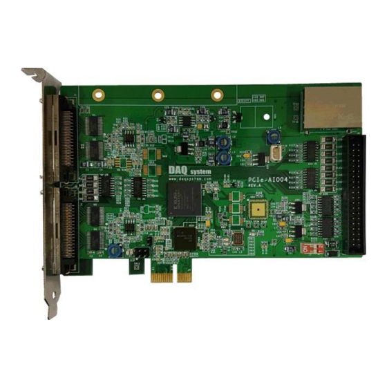
PCIe-AIO14
Windows, Windows XP, Windows 7, Windows 8 and Windows 10 are trademarks of Microsoft. We acknowledge t
hat the trademarks or service names of all other organizations mentioned in this document as their own property.
Information furnished by DAQ system is believed to be accurate and reliable. However, no responsibility is assumed by DAQ
system for its use, nor for any infringements of patents or other rights of third parties which may result from its use. No license is
granted by implication or otherwise under any patent or copyrights of DAQ system.
The information in this document is subject to change without notice and no part of this document may be copied or
reproduced without the prior written consent.
User's Manual
Copyrights 2005 DAQ system Co., LTD. All rights reserved.
PCIe-AIO14 User's Manual (Rev 1.2)
i
http://www.daqsystem.com
Advertisement
Table of Contents

Related Manuals for DAQ system PCIe-AIO14


Summary of Contents for DAQ system PCIe-AIO14
- Page 1 Information furnished by DAQ system is believed to be accurate and reliable. However, no responsibility is assumed by DAQ system for its use, nor for any infringements of patents or other rights of third parties which may result from its use. No license is granted by implication or otherwise under any patent or copyrights of DAQ system.
-
Page 2: Table Of Contents
PCIe-AIO14 User Manual (Rev 1.2) Contents Introduction 1.1 Function 1.2 Block Diagram Features Hardware 3.1 Board Switch Setup 3.2 I/O Connector(J1, J2) 3.3 Digital I/O Connector(J8) 3.4 Analog Signal MUX 3.5 Digital I/O Installation 4.1 Confirm Contents 4.2 Installation Sequence 4.3 Device Verification... -
Page 3: Introduction
PCIe-AIO14 User Manual (Rev 1.2) 1. Introduction The PCIe-AIO14 board is a PCI Express interface board with dedicated analog inputs. The 16-channel analog signal is multiplexed by port control, and the signal is variably sampled and converted by two ADCs. -
Page 4: Features
Output Signal: Open Collector, under 10kHz, 12~24V Board Size 152.4x101.1mm(PCB) Operation Temperature Range Operating Humidity Range (non-condensing) Software Kernel mode Driver/User mode DLL Windows XP SP2/7/8/10 32-bit, 64-bit, 4GB RAM Components PCIe-AIO14 board , Installation CD(with Sample Program) http://www.daqsystem.com - 2 -... -
Page 5: Hardware
PCIe-AIO14 User Manual (Rev 1.2) 3. Hardware This section explains how to install PCIe-AIO14 board in PC or other operation equipment. The following explains the board switch settings before installation, input connector description, and board installation. Board Switch Setup Explain the jumper and switch selection on the board. -
Page 6: I/O Connector(J1, J2)
PCIe-AIO14 User Manual (Rev 1.2) 3.2 I/O Connector(J1, J2) The PCIe-AIO14 board with 32-channel analog differential signal input has two VHDCI (Very High Density Cable Interconnect) 68-pin connectors, each receiving 16 signals. The 16-bit signal is one ADC input signal. Each connector is connected to a 4-bit digital input and output signal. - Page 7 PCIe-AIO14 User Manual (Rev 1.2) #14 Input (-), AINN14 Analog Ground, AGND #14 Input (+), AINP14 Digital Output, DOUT1 #12 Input (-), AIN12 Analog Ground, AGND #12 Input (+), AINP12 Digital Output, DOUT2 #10 Input (-), AINN10 Analog Ground, AGND...
- Page 8 PCIe-AIO14 User Manual (Rev 1.2) #23 Input (-), AINN23 Analog Ground, AGND #23 Input (+), AINP23 Digital Input, DIN7 #21 Input (-), AINN21 Analog Ground, AGND #21 Input (+), AINP21 Digital Ground, GND #19 Input (-), AINN19 Analog Ground, AGND...
-
Page 9: Digital I/O Connector(J8)
PCIe-AIO14 User Manual (Rev 1.2) 3.2.4 Digital I/O Connector(J8) BOX HEADER 40-pin J8 connector has 16 DIN8 to DIN23 digital input signals and 16 DOUT8 to DOUT23 digital output signals. Applicable connector is HIF3F-40PA-2.54DS (Hirose) or compatible product. [Table 3-3. J8 Connector Description]... -
Page 10: Analog Signal Mux
PCIe-AIO14 User Manual (Rev 1.2) 3.3 Ananlog Signal MUX Multichannel data acquisition is implemented by multiplexing time-division multiplexed (MUX) for 16 signal inputs into one ADC AINP0 AINP1 AINP2 AINP3 16 to 1 16 to 1 AINP28 AINP29 AINP30 AINP31... - Page 11 PCIe-AIO14 User Manual (Rev 1.2) 3.4 Digital I/O Circuit Digital input and output circuits that support 24-bit inputs and outputs, respectively, support shielded external interfaces by applying photocouplers. 3.4.1 Digital Input Circuit When the ground is connected to the DIN_COM pin and the 'HI' input signal is input to the DIN signal, the internal signal becomes 'LO' to sense the signal input.
-
Page 12: Installation
The board should be used in Windows XP SP2 over, Windows 7, Windows 8 and Windows 10. First, turn off the PC, insert the PCIe-AIO14 board into the PCI slot, and then power on the PC. The following describes the process of installing the device in Windows XP. - Page 13 PCIe-AIO14 User Manual (Rev 1.2) A window like the one below will appear and select "Install from a list or specific location" and click the "Next" button. [Fig 4-2. Software Installation Selection] In the window shown below, locate the CD or specific location where the driver is located and click the "Next"...
- Page 14 PCIe-AIO14 User Manual (Rev 1.2) When the "Hardware Installation" window appears and the following list of installed boards appears, click the "Continue" button. [Fig 4-4. Show the board you are installing] The "Completing the Found New Hardware Wizard" window appears and click the "Finish" button to finish.
-
Page 15: Device Verification
When the board installation is complete, check that the device is assigned to the OS. Control Panel - System - System Properties - Device Manager Select / Execute in order. Under Device Manager - Multifunction Adapters, make sure that the "PCIe-AIO14" device is shown as shown. [Fig 4-6. Devie Manager] http://www.daqsystem.com... -
Page 16: Software
PCIe-AIO14 User Manual (Rev 1.2) 5. Software It implements a library (API) for easy access to various functions of the PCIe-AIO14 board, and provides a sample program to the user. Operation Mode Appropriate API functions should be used depending on the operation such as the method of storing data collection samples in internal memory, the method of reading buffer data in the application, the use of trigger function, etc. -
Page 17: Normal Mode Operation Sequence
PCIe-AIO14 User Manual (Rev 1.2) Normal Mode Operation Sequence 5.2.1 Device Initialization OpenDAQDevice Windows handle allocation from the system, device initialization 5.2.2 Measurement time setting ADC_SetSamplingRate AD Sampling Rate Setup 5.2.3 Start measurement ADC_Run Initialize logic variables, Start data collection and create a data memory buffer 5.2.4 Checking the measurement status... -
Page 18: Trigger Mode Operation
PCIe-AIO14 User Manual (Rev 1.2) 5.3 Trigger Mode Operation Sequence 5.3.1 Device Initialization OpenDAQDevice Windows handle allocation from the system, device initialization 5.3.2 Measurement time setting ADC_SetSamplingRate ADC Sampling Rate Setup 5.3.3 Trigger Setup ADC_SetTriggerLevel, ADC_SetTriggerVolt Trigger channel, Trigger slope, Trigger level value setting and trigger motion control 5.3.4 Start measurement... -
Page 19: Sample Program
PCIe-AIO14 User Manual (Rev 1.2) Sample Program It implements a library (API) for easy access to various functions of the PCIe-AIO14 board, and provides a sample program to the user. [Fig 5-2. Program execution (continuous mode)] 5.4.1 Program UI Description [표... - Page 20 PCIe-AIO14 User Manual (Rev 1.2) Ch. Value The selected channel value is represented by HEX. Bit 0 is set to "CH0" and bit 15 is set to "CH15". Since "CH0" selection is AIN0, AIN1 is selected, and "CH15" selection is AIN30 and AIN31 because channel selection is for two ADCs.
- Page 21 PCIe-AIO14 User Manual (Rev 1.2) the channel number and the data value are displayed in the 36th and 37th sections. When the button 38 is pressed, the trigger data is drawn on the graph. 1’st Select the trigger channel. Set the operation conditions for the selected channel.
- Page 22 PCIe-AIO14 User Manual (Rev 1.2) value calculation is to be performed. Value Displays the data value of the selected channel. Clear Initialize the maximum, minimum, and deviation values. Max. Displays the measurement maximum value. Min. The measurement minimum value is displayed.
- Page 23 PCIe-AIO14 User Manual (Rev 1.2) 5.4.4 Single Block Mode Operation Sequence Single mode allocates a memory buffer to the library, stores it once in the buffer, and then automatically terminates the collection. The data stored in the current buffer is read in units of the set data block size.
- Page 24 PCIe-AIO14 User Manual (Rev 1.2) [Fig 5-3. Trigger Mode Data] 5.4.6 Sampling Timing Timing of acquisition and execution according to the set sampling rate is shown in the following figure. If more than one channel is selected, the time interval to the adjacent channel is the ADC highest sampling rate 2Msps and the interval between channel blocks maintains the time of the set sampling rate.
- Page 25 PCIe-AIO14 User Manual (Rev 1.2) References 1. PCI Express Base Specification, Revision 2.0 2. PCI Exprss to PCI/PCI-X Bridge Specification, Revision 1.0 3. PCI Local Bus Specification -- PCI-SIG 4. AN201 How to build application using APIs -- DAQ system 5.
Need help?
Do you have a question about the PCIe-AIO14 and is the answer not in the manual?
Questions and answers