Table of Contents
Advertisement
Quick Links
Advertisement
Table of Contents

Subscribe to Our Youtube Channel
Related Manuals for Westermo RedFox-5728-F4G-T24G-LV


Summary of Contents for Westermo RedFox-5728-F4G-T24G-LV
- Page 1 www.wester mo.com RedFox 5728 Series Industrial routing switches...
-
Page 2: Table Of Contents
Table of Contents 1. General Information ................ 3 1.1. Legal Information ..............3 1.2. About This Guide ..............3 1.3. Software Tools ..............3 1.4. License and Copyright for Included FLOSS ......... 3 1.5. WeOS ................. 3 2. Safety and Regulations ..............4 2.1. -
Page 3: General Information
Westermo reserves the right to revise this document or withdraw it at any time without prior notice. Under no circumstances shall Westermo be responsible for any loss of data or income or any special, incidental, and consequential or indirect damages howsoever caused. -
Page 4: Safety And Regulations
2. Safety and Regulations 2.1. Warning Levels Warning signs are provided to prevent personal injuries and/or damages to the product. The following levels are used: Level of warning Description Consequence Consequence personal injury material damage Indicates a potentially Possible death or major Major damage to the hazardous situation injury... -
Page 5: Safety Information
Before energising and connecting communication cables to the product, ensure a protective earthing conductor is first connected to the protective earthing terminal (only valid for metallic housings). Westermo recommends a cross-sectional area of at least 4 mm Upon removal of the product, disconnect the product from the power supply and all other communication ports before disconnecting the protective earthing conductor. - Page 6 PROTECTIVE FUSE It must be possible to disconnect manually from the power supply. Ensure compliance to national installation regulations. Replacing the internal fuse must only be performed by Westermo qualified personnel. POWER SUPPLY CONNECTION There are safety regulations governing the power source that can be used in conjunction with the product.
- Page 7 CLASS 1 LASER PRODUCT Do not look directly into a fibre optical port or any connected fibre, although the product is designed to meet the Class 1 Laser regulations and complies with 21 CFR 1040.10 and 1040.11. HANDLING OF SFP TRANSCEIVERS SFP transceivers are supplied with plugs to avoid contamination inside the optical port.
-
Page 8: Care Recommendations
If the product is not working properly, contact the place of purchase, the nearest Westermo distributor office or Westermo technical support. 2.4. Product Disposal This symbol means that the product shall not be treated as unsorted municipal waste when disposing of it. -
Page 9: Compliance Information
2.5. Compliance Information 2.5.1. Agency Approvals and Standards Compliance Type Approval/Compliance • EN 50121-4/IEC 62236-4, Railway signalling and telecommunications apparatus • EN/IEC 61000-6-2, Immunity industrial environments • EN/IEC 61000-6-4, Emission industrial environments • EN/IEC 61000-6-5, Immunity power station and substation environment •... -
Page 10: Simplified Declaration Of Conformity
2.5.4. Simplified Declaration of Conformity Hereby, Westermo declares that this product is in compliance with applicable EU directives and UK legislations. The full declaration of conformity and other detailed information is available at www.westermo.com/support/product-support. Figure 2. The European Conformity and the UK Conformity Assessment markings... -
Page 11: Product Description
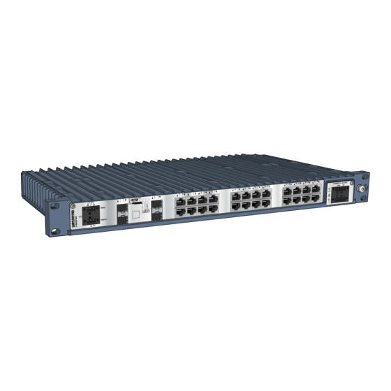
3. Product Description 3.1. Product Description RedFox-5728 takes communication reliability for substations to a new level. We know that in critical substation automation applications, even the loss of a single piece of data can disturb the operations, and that is why RedFox-5728 brings the highest reliability to your network. -
Page 12: Available Models
3.2. Available Models Art. no. Model No. of SFP ports No. of copper Layer ports 3641-4350 RedFox-5728-F4G-T24G-LV Layer 2 3641-4355 RedFox-5728-F4G-T24G-LVLV Layer 2 3641-4550 RedFox-5728-F4G-T24G-HV Layer 2 3641-4555 RedFox-5728-F4G-T24G-HVHV Layer 2 3641-4360 RedFox-5728-F16G-T12G-LV Layer 2 3641-4365 RedFox-5728-F16G-T12G-LVLV Layer 2 3641-4560... -
Page 13: Hardware Overview
3.3. Hardware Overview 11 12 21 22 23 24 27 28 NO C NC POWER 110-240 VAC / VDC Status N (-) L (+) AC/DC Digital in AC/DC Description Description I/O connection Console port Micro SD LED indicators 100/1000 Mbit/s SFP port (number 10/100/1000 Mbit/s TX ports (number depending on model) depending on model) - Page 14 Illustration Position Product Direction Description marking AC/DC1 L(+) Input Line/Phase (AC), positive (DC) N (-) L (+) AC/DC N(-) Input Neutral (AC), negative/return (DC) Input Functional earth Table 4. Power input HV Illustration Product marking Direction Description +DC1 Input Supply voltage COM +DC +DC2 Input...
-
Page 15: I/O Connection
WARNING - PREVENT ACCESS TO HAZARDOUS VOLTAGE CABLE Apply the protective cap (delivered with the HV and HVHV products) on the power cable, according to the illustrated steps below. To prevent accidentally pulling out wires, make sure the power cable and the wires are firmly attached to the protective cap. -
Page 16: Console Port
To insert the micro SD card correctly, turn the gold plated pins upwards. Figure 5. Insertion of micro SD card 3.4.5. SFP Transceivers The product supports UL and Westermo labelled SA-approved transceivers only. See Westermo's modular transceivers datasheets 100 Mbit and 1 Gbit for SA-approved RedFox 5728 Series... - Page 17 Each SFP slot can hold one SFP transceiver. See "Transceiver User Guide 6100-0000" for transceiver handling instructions, which also can be downloaded from the product support pages at www.westermo.com/support/product-support. In the event of contamination, the optical connectors in the SFP transceivers should only be cleaned by the use of forced nitrogen and some kind of cleaning stick.
-
Page 18: Led Indicators
3.5. LED Indicators Status Description Product has no power GREEN All OK, no alarm condition Alarm condition, or until product has started up. (Alarm conditions are configurable, see WeOS5 User Guide) RSTP/ RSTP disabled USR1 GREEN RSTP enabled BLINK Product selected as RSTP/STP root switch USR1 Configurable, see WeOS5 User Guide FRNT... -
Page 19: Dimensions
3.6. Dimensions Dimensions are stated in mm. 482,4 DETAIL A SCALE 1 : 1 7,2 (x4) Figure 6. Dimensional drawing, illustrated by a RedFox-5728-F16G-T12G-HVHV RedFox 5728 Series... -
Page 20: Installation
4. Installation 4.1. Mounting RedFox-5728 is designed for installation in 19" rack solutions, with a shallow depth of 240 millimetres. 4.1.1. Rack Mounting The product can be mounted in all directions inside a 19" apparatus cabinet. Use supplied M6x25 (Philips no. 3) or 1/4x1" screws. Statu s Digit al in Figure 7. -
Page 21: Specifications
5. Specifications 5.1. Interface Specifications NOTE - USE OF ANTISTATIC ARM-WRIST BAND To minimize the risk of exposing the unit to unintentional large static electric fields - if service and maintenance need to be performed during operation, always use an antistatic arm-wrist band. RedFox 5728 Series... - Page 22 Power port Rated voltage LV and LVLV models: 24-48 VDC HV and HVHV models: 110-240 VAC, 50-60 Hz, 110-240 VDC Operating voltage LV and LVLV models: 18-60 VDC HV and HVHV models: 85-264 VAC, 47-63 Hz, 85-264 VDC b.c. Rated current RedFox-5728-(E-)F4G-T24G-LV 1.08 A at 24 VDC RedFox-5728-(E-)F4G-T24G-LVLV...
- Page 23 Power port Tightening torque, terminal 0.34 Nm screw Tightening torque, screw 0.34 Nm flange For LV and LVLV models, only compliant Class I or Class II power supplies with SELV/PELV output shall be used with the product For HVHV models, AC/DC1 shall be regarded as the primary supply input, which gives the highest efficiency. When both AC/DC1 and AC/DC2 inputs are energized, some portion of the unit's power consumption will be drawn from AC/DC2, while AC/DC1 will utilize the majority of the power consumption.
- Page 24 I/O connection, Relay output Maximum 30 Ω Connect resistance Isolation to All other ports Connector Detachable screw terminal Conductor cross section 0.08-1.5 mm² (AWG 28-16). Use copper conductors only. (flexible) Stripping length cable 7 mm Cable temperature rating Minimum temperature rating of the cable to be connected to the field wiring terminals is +77 °C Tightening torque, terminal 0.22-0.25 Nm...
- Page 25 SFP ports Optical/Electrical specification IEEE std 802.3 Data rate 100 Mbit/s, 1 Gbit/s Duplex Full or half, manual or auto Transmission range Depending on transceiver Connector SFP slot holding fibre transceiver SFP ports are: RedFox-5728-F4G-T24G-HV and -HVHV: 1-4 RedFox-5728-F4G-T24G-HV, -HVHV and -LV: 1-4 RedFox-5728-F4G-T24G-HV, -HVHV, -LV and -LVLV: 1-4 RedFox-5728-F16G-T12G-HV and -HVHV: 1-6, 11-14, 19-22, 27-28 RedFox-5728-F16G-T12G-HV, -HVHV and -LV: 1-6, 11-14, 19-22, 27-28...
-
Page 26: Type Tests And Environmental Conditions
5.2. Type Tests and Environmental Conditions Environmental Basic Description Test levels phenomena standard EN 61000-4-2 Enclosure Contact: ±8 kV Air: ±15 kV Fast transients EN 61000-4-4 AC power port ±4 kV, direct coupling DC power port Earth port I/O port ±4 kV, capacitive coupling clamp Ethernet ports Surge... - Page 27 Environmental Basic Description Test levels phenomena standard Radiated RF EN 61000-4-3 Enclosure 20 V/m, 80% AM (1 kHz) at 80 MHz to immunity IEEE Std 2 GHz, Spot freq.: 80, 160, 380, 450, 900, C37.90.2 1600, 1850 MHz 10 V/m, 80% AM (1 kHz) at 2 to 6 GHz, Spot freq.: 2150, 3800 MHz 20 V/m, pulse keying (2 Hz) at 80 MHz to 1 GHz, Spot freq.: 1732, 1800 MHz...
- Page 28 Environmental Basic Description Test levels phenomena standard Temperatures EN 60068-2-1 Operational -40 to +70°C (-40 to +158°F) EN 60068-2-2 Storage and -50 to +85°C (-58 to +185°F) EN 60068-2-14 transport Humidity Operational 5-95 % relative humidity 680068-2-30 Storage and EN 60068-2-78 transport Altitude Operational...
- Page 29 Environmental Basic Description Test levels phenomena standard 8 to 500 Hz at 2g 5 sweep cycles in each axis (3x5), 1 octave/min EN 60068-2-64 Operational 2.3 m/s random, 5 to 2000 Hz, 3x1.5h IEEE 1613 Operational Class V.S.3 1 to 150 Hz at <30 mm/s Shock Operational Class 2, 10g/11 ms, 3x6 shocks...
-
Page 30: Revision Notes
6. Revision Notes Revision Date Change description Rev. F 2023-04 3.5 LED Indicators updated (ON; Blink deleted) Rev. E 2022-10 5.1 Interface Specifictions updated (rated current) Rev. D 2022-01 2.2 Safety Information updated; (Warning Safety during installation), 2.5.1 Agency Approvals and Standards Compliance updated, 2.5.2 FCC Part 15.105 Class A Notice added, 3.2 Available Models updated, 3.4.1 Power Input updated (table 5 and note), 5.1 Interface Specifictions updated (Power port table, Ethernet TX table, SFP ports table and footnote for... - Page 31 Westermo • Metallverksgatan 6, SE-721 30 Västerås, Sweden Tel +46 16 42 80 00 Fax +46 16 42 80 01 E-mail: info@westermo.com www.westermo.com 6641-25001 REV F 2023 04 @ Westermo Network Technologies AB, Sweden...
Need help?
Do you have a question about the RedFox-5728-F4G-T24G-LV and is the answer not in the manual?
Questions and answers