Westermo RedFox 5528 Series User Manual
Industrial routing switches
Hide thumbs
Also See for RedFox 5528 Series:
- User manual (32 pages) ,
- User manual (30 pages) ,
- User manual (32 pages)
Table of Contents
Advertisement
Quick Links
Advertisement
Table of Contents

Related Manuals for Westermo RedFox 5528 Series


Summary of Contents for Westermo RedFox 5528 Series
- Page 1 RedFox 5528 Series Industrial routing switches WeOS...
-
Page 2: Table Of Contents
4.1.1. Rack Mounting ............16 4.1.2. Wall Mounting ............16 4.2. Earth Connection ..............17 4.3. Cooling ................17 5. Specifications ................18 5.1. Interface Specifications ............18 5.2. Type Tests and Environmental Conditions ......... 21 6. Revision Notes ................24 RedFox 5528 Series... -
Page 3: General Information
Westermo reserves the right to revise this document or withdraw it at any time without prior notice. Under no circumstances shall Westermo be responsible for any loss of data or income or any special, incidental, and consequential or indirect damages howsoever caused. -
Page 4: Safety And Regulations
No personal injury Minor damage to the to avoid misuse of the product product, confusion or misunderstanding NOTICE Used for highlighting general, No personal injury Minor damage to the but important information product NOTE Table 1. Warning levels RedFox 5528 Series... -
Page 5: Safety Information
Before mounting, using or removing this product: Prevent access to hazardous voltage by disconnecting the product from all power supply. WARNING - HAZARDOUS VOLTAGE Do not open the connected product. Hazardous voltage may occur within this product when connected to power supply. RedFox 5528 Series... -
Page 6: Care Recommendations
To reduce the risk of fire, use only No. 26 (e.g. 24 AWG) UL listed or CSA certified Telecommunication Line Cord. 2.3. Care Recommendations Follow the care recommendations below to maintain full operation of the product and to fulfill the warranty obligations: RedFox 5528 Series... -
Page 7: Maintenance
• Do not use harsh chemicals, cleaning solvents or strong detergents to clean the product. • Do not paint the product. Paint can clog the product and prevent proper operation. If the product is not working properly, contact the place of purchase, nearest Westermo distributor office or Westermo Tech support. -
Page 8: Compliance Information
CAUTION - CORROSIVE GASES If the product is placed in a corrosive environment, it is important that all unused connector sockets are protected with a suitable plug, in order to avoid corrosion attacks on the gold plated connector pins. RedFox 5528 Series... -
Page 9: Simplified Declaration Of Conformity
2.8.4. Simplified Declaration of Conformity Hereby, Westermo declares that this product is in compliance with applicable EU directives. The full EU declaration of conformity and other detailed information is available at www.westermo.com/support/product-support. Figure 2. The European conformity marking RedFox 5528 Series... -
Page 10: Product Description
+165°F) can be achieved with no moving parts or cooling holes in the case. RedFox has been tested both by Westermo and external test labs to meet many standards regarding EMC, isolation, climate, vibration and shock, all to the highest levels suitable for heavy industrial environments and rail trackside application. -
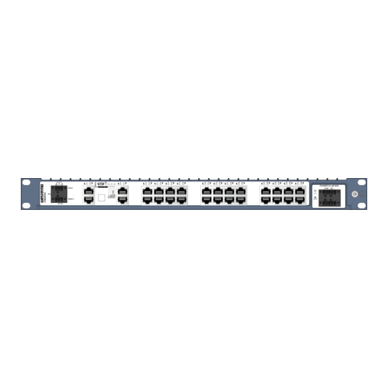
Page 11: Hardware Overview
Figure 3. Location of interface ports and LED indicators, illustrated by a RedFox-5528-F16G-T12G 3.4. Connector Information 3.4.1. Power Input and I/O Illustration Position Product marking Direction Description +DC1 Input Supply voltage +DC2 Input Supply voltage -COM Input Common -COM Input Common Table 3. Power input and I/O RedFox 5528 Series... -
Page 12: I/O Connection
The Status output is a potential free, opto-isolated, alternation (Form-C) solid-state relay. This can be configured to monitor various alarm events within the RFIR unit, see WeOS Management Guide. An external load in series with an external DC or AC voltage source is required for proper functionality. RedFox 5528 Series... -
Page 13: Console Port
VCP driver 3.4.4. SFP Transceivers The product supports Westermo labelled transceivers only. See Westermo's modular transceivers datasheets 100 Mbit and 1 Gbit for supported SFP transceivers for the RedFox series. Each SFP slot can hold one SFP transceiver. For supported transceivers, see SFP datasheets. -
Page 14: Led Indicators
USR2 Configurable, see WeOS Management Guide TX/FX No link ports GREEN Link established GREEN Data traffic indication FLASH YELLOW Port alarm and no link. Or if FRNT or RSTP mode, port is blocked. Table 6. LED indicators RedFox 5528 Series... -
Page 15: Dimensions
3.6. Dimensions Dimensions are stated in mm. Grounding Point Screw M5 x 0.8 mm - Roll tap true all DETAIL A SCALE 1 : 1 7,2 (4x) Figure 5. Dimensional drawing Illustrated by RedFox-5528-F4G-T24G-HV/LV. RedFox 5528 Series... -
Page 16: Installation
The product can be mounted in all directions inside a 19" apparatus cabinet. Use M6x25 or 1/4x1". St at Figure 6. Rack mounted product 4.1.2. Wall Mounting The product can be wall mounted in all directions. Use maximum 6.4 mm or 1/4" screws. RedFox 5528 Series... -
Page 17: Earth Connection
For wall mounting in an area without forced ventilation, a minimum spacing of 45 mm (1.75") above/below and 10 mm (0.4") left/right is recommended. For areas with forced ventilation, no minimal spacing is required as long as the temperature of the rear cooling plates does not exceed +85ºC (+185ºF). RedFox 5528 Series... -
Page 18: Specifications
2x nominal current Polarity Reverse polarity protected Redundant power input Isolation All other ports Connector Detachable screw terminal Conductor cross section 0.2-2.5 mm² (AWG 24-12) Stripping length cable 7 mm Tightening torque, terminal 0.5 - 0.6 Nm screw RedFox 5528 Series... - Page 19 Connector Detachable screw terminal Conductor cross section 0.14 - 1.5 mm² (AWG 28-16) Stripping length cable 7 mm Tightening torque, terminal 0.22 - 0.25 Nm screw Terminal torque, screw flange 0.3 Nm Maximum voltage/current 60 VDC/80 mA RedFox 5528 Series...
- Page 20 Up to 480 Mbps (high-speed mode) Circuit type SELV Maximum supply current 100 mA Connector USB Micro B connector in device mode Micro SD Electrical specification Secure Digital 2.0 Circuit type SELV Maximum supply current 100 mA Connector Micro SD connector RedFox 5528 Series...
-
Page 21: Type Tests And Environmental Conditions
EN 60950-1 Power port to all 1500 VAC rms, 60 s other ports Ethernet ports to all other ports Gbps Ethernet 1500 VAC rms, 60 s ports to all other ports Table 7. EMC and electrical conditions RedFox 5528 Series... - Page 22 13.2-100 Hz, 1.0 grms, 150 minutes per (random) axis 5-2000 Hz, rms 2.3 m/s ,1.5h Shock Operational 30 g, 11 ms 60068-2-27 Enclosure EN 60950-1 Aluminum Fire enclosure Weight 3.8 kg Degree of protection EN 60529 Enclosure IP40 RedFox 5528 Series...
- Page 23 Test levels phenomena standard Cooling Convection Refer to "Safety and Regulations" chapter regarding touch temperature Method 3, 21 days corresponds to Harsh Industrial Environment G3 which is defined in ANSI/ISA 17.04: 2015 Table 8. Environmental and mechanical conditions RedFox 5528 Series...
-
Page 24: Revision Notes
Interface Specifications updated - inrush current, SFP ports, 5.2 Type Tests and Environmental Conditions updated - Surge updated, Corrosive gased added, Vibration updated, Radiated RF emission and Conducted RF emission updated Rev. A 2017-07 First issue of the user guide RedFox 5528 Series... - Page 25 RedFox 5528 Series...
- Page 26 RedFox 5528 Series...
- Page 27 RedFox 5528 Series...
- Page 28 Westermo • SE-635 35 Stora Sundby, Sweden Tel +46 16 42 80 00 Fax +46 16 42 80 01 E-mail: info@westermo.com www.westermo.com 6641-22820 REV D 2019 06 Westermo Network Technologies AB, Sweden...
Need help?
Do you have a question about the RedFox 5528 Series and is the answer not in the manual?
Questions and answers