Table of Contents
Advertisement
Quick Links
Advertisement
Table of Contents

Subscribe to Our Youtube Channel
Related Manuals for Westermo RedFox-5528-E-T28G-LV


Summary of Contents for Westermo RedFox-5528-E-T28G-LV
- Page 1 www.wester mo.com RedFox 5528 Series Industrial routing switches...
-
Page 2: Table Of Contents
Table of Contents 1. General Information ................ 3 1.1. Legal Information ..............3 1.2. About This Guide ..............3 1.3. Software Tools ..............3 1.4. License and Copyright for Included FLOSS ......... 3 1.5. WeOS ................. 3 2. Safety and Regulations ..............4 2.1. -
Page 3: General Information
Westermo reserves the right to revise this document or withdraw it at any time without prior notice. Under no circumstances shall Westermo be responsible for any loss of data or income or any special, incidental, and consequential or indirect damages howsoever caused. -
Page 4: Safety And Regulations
2. Safety and Regulations 2.1. Warning Levels Warning signs are provided to prevent personal injuries and/or damages to the product. The following levels are used: Level of warning Description Consequence Consequence personal injury material damage Indicates a potentially Possible death or major Major damage to the hazardous situation injury... -
Page 5: Safety Information
Before energising and connecting communication cables to the product, ensure a protective earthing conductor is first connected to the protective earthing terminal (only valid for metallic housings). Westermo recommends a cross-sectional area of at least 4 mm Upon removal of the product, disconnect the product from the power supply and all other communication ports before disconnecting the protective earthing conductor. - Page 6 PROTECTIVE FUSE It must be possible to disconnect manually from the power supply. Ensure compliance to national installation regulations. Replacing the internal fuse must only be performed by Westermo qualified personnel. POWER SUPPLY CONNECTION There are safety regulations governing the power source that can be used in conjunction with the product.
-
Page 7: Care Recommendations
If the product is used in a manner not according to specification, the protection provided by the equipment may be impaired. If the product is not working properly, contact the place of purchase, the nearest Westermo distributor office or Westermo technical support. RedFox 5528 Series... -
Page 8: Product Disposal
2.4. Product Disposal This symbol means that the product shall not be treated as unsorted municipal waste when disposing of it. It needs to be handed over to an applicable collection point for recycling electrical and electronic equipment. By ensuring the product is disposed of correctly, you will help to reduce hazardous substances and prevent potential negative consequences to both the environment and human health, which could be caused by inappropriate disposal. -
Page 9: Iec/Ul 62368-1 Notice
Table 3. EN/IEC/UL 62368-1 notice 2.5.4. UL 62368-1 DC Mains Notice In accordance with UL 62368-1, Annex DVD and DVH then Westermo does not recommend using the mechanical enclosure/chassis (PE) as a conductive part of the sourced earthed DC power system in a DC mains distribution networks. If so, the... -
Page 10: Fcc Part 15.105 Class B Notice
2.5.8. Simplified Declaration of Conformity Hereby, Westermo declares that this product is in compliance with applicable EU directives and UK legislations. The full declaration of conformity and other detailed information is available at www.westermo.com/support/product-support. -
Page 11: Product Description
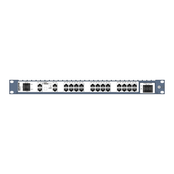
3. Product Description 3.1. Product Description The RedFox 5528 series is designed for the core of large high-performance industrial networks and has been developed to cater to the needs of current and future industrial data networks, combining outstanding performance, durability and reliability. These switches are ideal for handling the big data and high bandwidth requirements typically found within transportation, manufacturing, energy, smart cities and other applications. -
Page 12: Available Models
3.2. Available Models Art. no. Model No. of No. of copper ports ports 3641-4500 RedFox-5528-T28G-LV 24-48 3641-4400 RedFox-5528-E-T28G-LV 3641-4508 RedFox-5528-T28G-HV 110-240 V 3641-4408 RedFox-5528-E-T28G-HV AC/DC 3641-4510 RedFox-5528-F4G-T24G-LV 24-48 3641-4410 RedFox-5528-E-F4G-T24G-LV 3641-4518 RedFox-5528-F4G-T24G-HV 110-240 V 3641-4418 RedFox-5528-E-F4G-T24G-HV AC/DC 3641-4520 RedFox-5528-F16G-T12G-LV 24-48... -
Page 13: Connector Information
3.4. Connector Information 3.4.1. Power Input Illustration Product marking Direction Description +DC1 Input Supply voltage COM +DC +DC2 Input Supply voltage -COM Input Common -COM Input Common Table 4. Power input LV models Illustration Position Product Direction Description marking AC/DC1 L(+) Input Line/Phase (AC),... -
Page 14: I/O Connection
The Status output is a potential free, opto-isolated, alternation (Form-C) solid-state relay. This can be configured to monitor various alarm events within the product, see WeOS user documentation at www.westermo.com. An external load in series with an external DC voltage source is required for proper functionality. -
Page 15: Sfp Transceivers
3.4.5. SFP Transceivers The product supports UL and IEC certified transceivers only. See Westermo's modular transceivers datasheets 100 Mbit and 1 Gbit for supported SFP transceivers, which can be downloaded from the product support pages at www.westermo.com/support/product- support. Each SFP slot can hold one SFP transceiver. See "Transceiver User Guide 6100-0000" for transceiver handling instructions, which also can be downloaded from the product support pages at www.westermo.com/support/product-support. -
Page 16: Led Indicators
3.5. LED Indicators Status Description Product has no power GREEN All OK, no alarm condition Alarm condition, or until product has started up. (Alarm conditions are configurable, see WeOS5 User Guide) RSTP/ RSTP disabled USR1 GREEN RSTP enabled BLINK Product selected as RSTP/STP root switch USR1 Configurable, see WeOS5 User Guide FRNT... -
Page 17: Dimensions
3.6. Dimensions Dimensions are stated in mm. 482,4 7,2 (x4) Figure 5. Dimensional drawing RedFox 5528 Series... -
Page 18: Installation
4. Installation 4.1. Mounting RedFox is designed for installation in 19" rack solutions according to ETSI standard, with a shallow depth of 240 millimetres. It can also be wall mounted as an installation option. 4.1.1. Rack Mounting The product can be mounted in all directions inside a 19" apparatus cabinet. Use supplied M6x25 (Philips no. -
Page 19: Cooling
4.3. Cooling This product relies on convection cooling. To avoid obstruction of the airflow around the product, follow the spacing recommendations. For mounting in 19" apparatus cabinet without forced ventilation, a minimal spacing of 1U according to IEC 60297 or 45 mm (1.75") above/below is recommended. With forced ventilation, no minimal spacing is required as long as the temperature of the rear cooling plates does not exceed +85ºC (+185ºF). -
Page 20: Specifications
5. Specifications 5.1. Interface Specifications Power port Rated voltage For LV models: 24-48 VDC For HV models: 110-240 V AC/DC Operating voltage For LV models: 18-60 VDC For HV models: 85-264 VAC 47-63 Hz, 85-264 VDC Rated current RedFox-5528-(E-)T28G-LV: 0.95 A at 24 VDC 0.49 A at 48 VDC RedFox-5528-(E-)T28G-HV: 0.12 A at 240 V AC/DC... - Page 21 Power port Cable temperature rating Minimum temperature rating of the cable to be connected to the field wiring terminals is +77 °C Tightening torque, terminal 0.34 Nm screw Tightening torque, screw 0.34 Nm flange Shielded cable Not required Measured for 1 second at startup Recommended external supply current capability for proper startup I/O connection, Digital input Isolation to...
- Page 22 I/O connection, Relay output Maximum 30 Ω Connect resistance Isolation to All other ports Connector Detachable screw terminal Conductor cross section 0.08 - 1.5 mm² (AWG 28-16). Use copper conductors only. Stripping length cable 7 mm Cable temperature rating Minimum temperature rating of the cable to be connected to the field wiring terminals is +77 °C Tightening torque, terminal 0.22 - 0.25 Nm...
- Page 23 SFP ports Optical/Electrical specification IEEE std 802.3 Data rate 100 Mbit/s, 1000 Mbit/s Duplex Full or half, manual or auto Transmission range Depending on transceiver Connector SFP slot holding fibre transceiver SFP ports are: RedFox-5528-(E-)F4G-T24G-LV/HV: 1-4 RedFox-5528-(E-)F16G-T12G-LV/HV: 1-6, 11-14, 19-22, 27-28 100 Mbit/s or 1000 Mbit/s tranceiver supported Console port Electrical specification...
-
Page 24: Type Tests And Environmental Conditions
5.2. Type Tests and Environmental Conditions Environmental Basic Description Test levels phenomena standard EN 61000-4-2 Enclosure Contact: ±6 kV Air: ±8 kV Fast transients EN 61000-4-4 Power port ± 2 kV I/O ports Earth port Surge 1.2/50 µs EN 61000-4-5 Power port LV models: L-E: ±... - Page 25 Environmental Basic Description Test levels phenomena standard (FCC Part 15 B) CISPR 22 Ethernet ports LV models: Class B HV models: Class A Dielectric strength EN/IEC/UL Power port to all LV models: 1500 VAC rms, 60 s 62368-1 other ports I/O port to all other ports Ethernet ports to...
- Page 26 Environmental Basic Description Test levels phenomena standard Temperatures EN 60068-2-1 Operational For LV models: -40 to +74°C (-40 to EN 60068-2-2 +165°F) For HV models: -40 to +70°C (-40 to +158°F) Storage and -50 to +85°C (-58 to +185°F) transport Humidity EN 60068-2-30 Operational...
- Page 27 Environmental Basic Description Test levels phenomena standard Overvoltage EN/IEC/UL HV models: OVC II category 61010-1, EN/IEC/UL 62368-1 Insulation class EN/IEC/UL HV models: Class I equipment 61010-1 Location Indoor use For LV models only Method 3, 21 days corresponds to Harsh Industrial Environment G3 which is defined in ANSI/ISA 17.04: 2015 Table 10.
-
Page 28: Revision Notes
5.1 Interface Specifications updated (Power) Rev. G 2020-10 Westermo logo updated, illustrations throughout user guide updated with blue colour, 2.2 Safety information; warnings updated, 2.3 Care Recommendations; text updated, 2.5.1 Agency Approvals and Standards Compliance; table updated, 2.5.2 new chapter, 2.5.3 FCC Part 15.105 Class B Notice;... - Page 29 Revision Date Change description 1.3 Software tools updated, 2.1 Warning levels updated (Caution), 2.2 Safety information updated, 2.3 Care recommendations updated, 2.5 Fibre optic handling updated, 2.7 Product disposal updated, 2.8.1 Agency approvals and standard compliance updated, 2.8.4 Simplified declaration of conformity updated, 3.1 Product description updated, 3.2 Available models updated, 3.3 Hardware overview updated, 3.4.1 Power input and I/O updated, 3.5 LED indicators updated, 3.6 Dimensions updated,...
- Page 30 Westermo • Metallverksgatan 6, SE-721 30 Västerås, Sweden Tel +46 16 42 80 00 Fax +46 16 42 80 01 E-mail: info@westermo.com www.westermo.com 6641-22820 REV M 2023 10 @ Westermo Network Technologies AB, Sweden...
Need help?
Do you have a question about the RedFox-5528-E-T28G-LV and is the answer not in the manual?
Questions and answers