
Subscribe to Our Youtube Channel
Related Manuals for Westermo RedFox Industrial EX Series


Summary of Contents for Westermo RedFox Industrial EX Series
- Page 1 User Guide 6641-22400 RedFox Industrial E X - S E R I E S WeOS Industrial Routing Switch www.westermo.com...
-
Page 2: Software Tools
Under no circumstances shall Westermo be responsible for any loss of data or income or any special, incidental, and consequential or indirect damages howsoever caused. -
Page 3: Before Installation
Do not use or store the unit in dusty, dirty areas, connectors as well as other mechanical part may be damaged. If the unit is not working properly, contact the place of purchase, nearest Westermo distributor office or Westermo Tech support. -
Page 4: Atex Certification
ATEX certification ATEX certification number Baseefa15ATEX0093X Standards EN 60079-0:2012, EN 60079-15:2010, EN 60079-28: 2007 Certification code RFI-211-T3G, RFI-219-T3G: Ex nA IIC T4 Gc (–40°C ≤ Ta ≤ +70°C) all other models: Ex nA [op is T4] IIC T3 Gc (–40°C ≤ Ta ≤ +70°C) ATEX code II 3G Specific Conditions of Use... - Page 5 SFP option approved transceivers SFP Transceivers, 100 Mbit 1100-0131 MLC2, Multimode, LC-Connector, 2 km, 1310 nm 1100-0132 SLC20, Singlemode, LC-Connector, 20 km, 1310 nm 1100-0133 SLC40, Singlemode, LC-Connector, 40 km, 1310 nm 1100-0134 SLC80, Singlemode, LC-Connector, 80 km, 1550 nm 1100-0140 SLC120, Singlemode, LC-Connector, 120 km, 1550 nm BiDi Transceivers, 100 Mbit 1100-0145 SLC15-BiDi-A, Singlemode, BiDi, 20 km, 1310 nm TX, 1550 nm RX...
- Page 6 ATEX-Zertifizierung ATEX-Zulassungsnummer Baseefa15ATEX0093X Standards EN 60079-0:2012, EN 60079-15:2010, EN 60079-28:2007 Zertifizierungscode RFI-211-T3G, RFI-219-T3G: Ex nA IIC T4 Gc (–40°C ≤ Ta ≤ +70°C) alle anderen Modelle: Ex nA [op is T4] IIC T3 Gc (–40°C ≤ Ta ≤ +70°C) ATEX-Code II 3G Spezifische Einsatzbedingungen Die Geräte müssen in einem Bereich welcher einem maximalen Verschmutzungsgrad...
- Page 7 Für SFP-Option zugelassene Transceiver SFP-Transceiver, 100 Mbit 1100-0131 MLC2, Multimode, LC-Anschluss, 2 km, 1310 nm 1100-0132 SLC20, Singlemode, LC-Anschluss, 20 km, 1310 nm 1100-0133 SLC40, Singlemode, LC-Anschluss, 40 km, 1310 nm 1100-0134 SLC80, Singlemode, LC-Anschluss, 80 km, 1550 nm 1100-0140 SLC120, Singlemode, LC-Anschluss, 120 km, 1550 nm BiDi-Transceiver, 100 Mbit 1100-0145 SLC15-BiDi-A, Singlemode, BiDi, 20 km, 1310 nm TX, 1550 nm RX 1100-0146 SLC15-BiDi-B, Singlemode, BiDi, 20 km, 1550 nm TX, 1310 nm RX...
- Page 8 Certification ATEX Numéro de certification ATEX Baseefa15ATEX0093X Normes EN 60079-0:2012, EN 60079-15:2010, EN 60079-28:2007 Code de certification RFI-211-T3G, RFI-219-T3G: Ex nA IIC T4 Gc (–40°C ≤ Ta ≤ +70°C) tous les autres modèles: Ex nA [op is T4] IIC T3 Gc (–40°C ≤ Ta ≤ +70°C) Code ATEX II 3G Conditions spéciales d'utilisation...
- Page 9 Transmetteurs optionnels SFP certifiés Transmetteurs SFP, 100 Mbit 1100-0131 MLC2, multimode, connecteur LC, 2 km, 1310 nm 1100-0132 SLC20, monomode, connecteur LC, 20 km, 1310 nm 1100-0133 SLC40, monomode, connecteur LC, 40 km, 1310 nm 1100-0134 SLC80, monomode, connecteur LC, 80 km, 1550 nm 1100-0140 SLC120, monomode, connecteur LC, 120 km, 1550 nm Transmetteurs Bi-Di, 100 Mbit 1100-0145 SLC15 Bi-Di A, monomode, Bi-Di, 20 km, 1310 nm TX, 1550 nm, RX...
-
Page 10: Iecex Certification
IECEx certification IECEx certification number IECExBAS15.0066X Standards IEC 60079-0:2011, IEC 60079-15:2010, IEC 60079-28: 2006 Certification code RFI-211-T3G, RFI-219-T3G: Ex nA IIC T4 Gc (–40°C ≤ Ta ≤ +70°C) all other models: Ex nA [op is T4] IIC T3 Gc (–40°C ≤ Ta ≤ +70°C) Specific Conditions of Use The equipment must be installed in an area of not more than pollution degree 2 in accordance with IEC 60664-1, and in an enclosure that provides a minimum degree of... - Page 11 SFP option approved transceivers SFP Transceivers, 100 Mbit 1100-0131 MLC2, Multimode, LC-Connector, 2 km, 1310 nm 1100-0132 SLC20, Singlemode, LC-Connector, 20 km, 1310 nm 1100-0133 SLC40, Singlemode, LC-Connector, 40 km, 1310 nm 1100-0134 SLC80, Singlemode, LC-Connector, 80 km, 1550 nm 1100-0140 SLC120, Singlemode, LC-Connector, 120 km, 1550 nm BiDi Transceivers, 100 Mbit 1100-0145 SLC15-BiDi-A, Singlemode, BiDi, 20 km, 1310 nm TX, 1550 nm RX...
-
Page 12: Cleaning Of The Optical Connectors
Note. Fibre Optic Handling Fibre optic equipment needs special treatment. It is very sensitive to dust and dirt. If the fibre will be disconnected from the unit the protective hood on the transmitter/ receiver must be connected. The protective hood must be kept on during transportation. The fibre optic cable must also be handle the same way. -
Page 13: Agency Approvals And Standards Compliance
Agency approvals and standards compliance Art.no Denomination Type Approval/compliance 3641-5100 RFI-219-T3G-EX EN 50121-4, Railway applications – Electromagnetic compatibility – Emission and immunity of the signalling and 3641-5110 RFI-211-T3G-EX telecommunications apparatus 3641-5200 RFI-215-F4G-T3G-EX EN 61000-6-1, Electromagnetic compatibility – Immunity 3641-5210 RFI-207-F4G-T3G-EX for residential environments 3641-5300 RFI-219-F4G-T7G-EX... -
Page 14: Safety Control Drawing
Safety control drawing Direction / Position Input / Output values description IO / Status + = 60 VDC max IO / Status – = 80 mA max IO / Digital in + = 60 VDC max IO / Digital in – = 2.9 mA max Position Direction / Input/output values... - Page 15 Safety control drawing Position Direction* / description Input/output values In/out / TD+ In/out / TD– In/out / RD+ Per port: Not connected U = ± 1 V (4V/us) I = ± 20 mA Not connected Data rate: In/out / RD– 10/100 Mbit/s Not connected Not connected...
-
Page 16: Declaration Of Conformity
Declaration of Conformity Westermo Teleindustri AB Declaration of Conformity The manufacturer Westermo Teleindustri AB SE-640 40 Stora Sundby, Sweden Herewith declares that the product(s) Type of product Models Industrial Ethernet Switch RFI-x19-T3G-y, RFI-x03-T3G , RFI-x11-T3G-y, RFI-x15-F4G-T3G-y, RFI-x07-F4G-T3G-y, RFI-x19-F4G-T7G-y, RFI-x11-F4G-T7G-y, RFI-x19-F4G-T7G-F8-y is in conformity with the following EU directive(s). -
Page 17: Type Tests And Environmental Conditions
Type tests and environmental conditions Phenomena Test Description Test levels EN 61000-4-2 Enclosure contact ± 6 kV Enclosure air ± 8 kV RF field AM modulated IEC 61000-4-3 Enclosure 20 V/m 80% AM (1 kHz), 80 – 2700 MHz 10 V/m 80% AM (1 kHz), 2700 – 6000 MHz Fast transient EN 61000-4-4 Signal ports... - Page 18 The RedFox is also able to provide secure remote access to these networks across insecure connections by acting as a VPN endpoint. RedFox Industrial models Westermo Denomination Description article number 3 x 10/100/1000 Mbit/s, Ethernet TX, RJ-45...
-
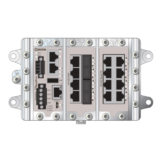
Page 19: Specification
Housing Description Depending on RedFox model, the size of the enclosure may vary. There are two sizes available, a two-slot housing and a three-slot housing. Regardless of RedFox model, the slot on the far left will always be occupied by the power and CPU interface. - Page 20 The isolated power supply has redundant power inputs and allows for a wide operating voltage range (see interface specification). The digital IO-port can be used for monitoring the unit (see Westermo OS management guide). The CPU module holds several interfaces. Three RJ-45 connectors with support for Ethernet 1000BaseTX, a USB port for easy save/load of system configuration and a console port.
-
Page 21: Interface Specifications
Interface specifications Power and CPU Rated voltage 20 to 48 VDC Operating voltage 16 to 60 VDC Rated frequency Polarity Reverse polarity protected Redundant power input Isolation to All other Connection Detachable screw terminal Connector size 0.2 – 2.5 mm (AWG 24 –... - Page 22 Connection to console port The console port can be used to connect to the CLI (Command Line Interface). The console connector is a micro USB cable that connects to a FTDI FT232R USB to serial converter internally. For drivers please see www. ftdichip.com and download the appropriate VCP driver.
- Page 23 Electrical specification USB 2.0 host interface Data rate High speed 480mbit/s Circuit type SELV Maximum supply current 500 mA Isolation to All other except Console Connection USB receptacle connector type A Conductive housing IO / Relay output 30 W Connect resistance Isolation to All other Connection...
- Page 24 Position Direction Description In/Out BI_DA+ In/Out BI_DA– In/Out BI_DB+ In/Out BI_DC+ In/Out BI_DC– In/Out BI_DB– In/Out BI_DD+ In/Out BI_DD– Shield In/Out Connected to PE Position Direction* Description VBUS In/Out D– In/Out Console Shield In/Out Connected to PE (see more information on page 13) * Direction relative this unit.
- Page 25 Power connection 4-position Product marking Direction Description No. 1 +DC1 Input Supply voltage input DC1 No. 2 +DC2 Input Supply voltage input DC2 No. 3 -COM Input Common No. 4 -COM Input Common Lynx supports redundant power connection. The positive inputs are +DC1 and +DC2, the negative input for both supplies are –COM.
-
Page 26: Led Indicators Power/Cpu
LED indicators Power/CPU Status Description Unit has no power. GREEN All OK, no alarm condition. Alarm condition, or until unit has started up. (Alarm conditions are configurable, see ''WeOS Management Guide''). BLINK Location indicator ("Here I am!"). Activated when connected to IPConfig Tool, or upon request from Web or CLI. -
Page 27: Interface Modules
Interface modules 8 copper ports All ports support category 5e cable or better and can handle cable lengths up to 150 m (492 ft). Interface specifications 8 copper ports Electrical specification IEEE std 802.3. 2005 Edition Data rate 10 Mbit/s or 100 Mbit/s, manual or auto Duplex Full or half, manual or auto Circuit type... - Page 28 LED indicators 8 copper ports Status Description Copper ports 1 – 8 No link. GREEN Link established. GREEN FLASH Data traffic indication. YELLOW Port alarm and no link. Or if FRNT, RSTP or Link Aggregation mode, port is blocked. Position Direction* Description In/Out...
- Page 29 The F4G interface has four SFP slots supporting Ethernet 10/100/1000BaseFX/X. Each slot can hold one SFP transceiver for copper or fibre cable. For supported transceivers see SFP transceivers user guide (art no. 6100-0000) available at www. westermo.com. Interface specifications Optical/Electrical specification IEEE std 802.3.
- Page 30 LED indicators F4G Status Description Fibre ports 1 – 4 No link. GREEN Link established. GREEN FLASH Data traffic indication. YELLOW Port alarm and no link. Or if FRNT, RSTP or Link Aggregation mode, port is blocked. Position Direction* Description Receive port Transmit port * Direction relative this unit.
- Page 31 LED indicators F8 Status Description Fibre ports 1 – 8 No link. GREEN Link established. GREEN FLASH Data traffic indication. YELLOW Port alarm and no link. Or if FRNT, RSTP or Link Aggregation mode, port is blocked. Position Direction* Description Receive port Transmit port * Direction relative this unit.
- Page 32 F4G-T4G, 4 SFP slots and 4 Gbit copper ports The F4G-T4G interface has four SFP slots supporting Ethernet BaseFX/X and four RJ-45 connectors supporting Ethernet 10/100/1000BaseTX/T. Each SFP slot can hold one SFP transceiver for copper or fibre cable. Fibre transceiver distances range from 550 m (0.34 mi) to 120 km (74,6 mi).
- Page 33 LED indicators F4G-T4G Status Description Copper ports 1 – 4 No link. Fibre ports 5 – 8 GREEN Link established. GREEN FLASH Data traffic indication. YELLOW Port alarm and no link. Or if FRNT, RSTP or Link Aggregation mode, port is blocked. Position Direction* Description...
-
Page 34: Sfp Transceivers
SFP Transceivers See SFP Transceivers User Guide 6100-0000 for supported SFP transceivers. Note: The unit supports Westermo labelled transceivers only. Deviations With copper transceiver 1100-0148 the specified operating temperature on the RFI-series is 0 to 50ºC. FRNT reconfiguration times can not be guaranteed with copper transceivers. -
Page 35: Wall Mounting
Snap on mounting, see figure. Note! For proper vibration and chock performance Westermo recommends standard top-hat DIN-rail TH 35-15 according to EN 60715. Removal Press down the support at the back of the unit using a screwdriver. -
Page 36: Getting Started
Getting Started This product runs Westermo Operating System (WeOS) which provides several management tools that can be used for configuration of the unit. • WeConfig WeConfig is a Network configuration management tool (NCM) made for commissioning and maintenance of components in a network. -
Page 37: Referring Documents
Referring documents Type Description Document number Management Guide Westermo OS management guide 6101-3201 Cable factory reset on RedFox Industrial It is possible to set the unit to factory default settings by using a standard (straight) Ethernet RJ-45 cable. 1. Power off the switch and disconnect all Ethernet cables (including copper and fibre). - Page 38 6641-22400...
- Page 39 6641-22400...
-
Page 40: Sales Units
France Singapore Other Offices infos@westermo.fr sales@westermo.com.sg www.westermo.fr www.westermo.com Germany Sweden info@westermo.de info.sverige@westermo.se www.westermo.de www.westermo.se For complete contact information, please visit our website at www.westermo.com/contact or scan the QR code REV. C 6641-22400 2017-04 Westermo Teleindustri AB, Sweden...
Need help?
Do you have a question about the RedFox Industrial EX Series and is the answer not in the manual?
Questions and answers