Westermo RedFox 5528 Series User Manual
Industrial routing switches
Hide thumbs
Also See for RedFox 5528 Series:
- User manual (28 pages) ,
- User manual (30 pages) ,
- User manual (32 pages)
Table of Contents
Advertisement
Quick Links
Advertisement
Table of Contents

Related Manuals for Westermo RedFox 5528 Series


Summary of Contents for Westermo RedFox 5528 Series
- Page 1 RedFox 5528 Series Industrial routing switches...
-
Page 2: Table Of Contents
4.1.1. Rack Mounting ............18 4.1.2. Wall Mounting ............18 4.2. Earth Connection ..............18 4.3. Cooling ................18 5. Specifications ................20 5.1. Interface Specifications ............20 5.2. Type Tests and Environmental Conditions ......... 24 6. Revision Notes ................28 RedFox 5528 Series... -
Page 3: General Information
Westermo reserves the right to revise this document or withdraw it at any time without prior notice. Under no circumstances shall Westermo be responsible for any loss of data or income or any special, incidental, and consequential or indirect damages howsoever caused. -
Page 4: Safety And Regulations
No personal injury Minor damage to the to avoid misuse of the product product, confusion or misunderstanding NOTICE Used for highlighting general, No personal injury Minor damage to the but important information product NOTE Table 1. Warning levels RedFox 5528 Series... -
Page 5: Safety Information
WARNING - PROTECTIVE FUSE It must be possible to disconnect manually from the power supply. Ensure compliance to national installation regulations. Replacing the internal fuse must only be performed by Westermo qualified personell. RedFox 5528 Series... - Page 6 CAUTION - CLASS 1 LASER PRODUCT Do not look directly into a fibre optical port or any connected fibre, although the product is designed to meet the Class 1 Laser regulations and complies with 21 CFR 1040.10 and 1040.11. RedFox 5528 Series...
-
Page 7: Care Recommendations
If the product is used in a manner not according to specification, the protection provided by the equipment may be impaired. If the product is not working properly, contact the place of purchase, nearest Westermo distributor office or Westermo technical support. -
Page 8: Product Disposal
This product generates, uses, and can radiate radio frequency energy and, if not installed and used in accordance with the user manual, may cause harmful interference to radio RedFox 5528 Series... -
Page 9: Fcc Part 15.105 Class B Notice
2.5.5. Simplified Declaration of Conformity Hereby, Westermo declares that this product is in compliance with applicable EU directives. The full EU declaration of conformity and other detailed information is available at www.westermo.com/support/product-support. -
Page 10: Product Description
The switches are also prepared for routing acceleration, extended cybersecurity and time synchronization IEEE 1588v2 applications, making them an ideal solution to meet future security and bandwidth requirements. RedFox 5528 Series... -
Page 11: Available Models
RedFox-5528-E-F4G-T24G-LV 3641-4515 RedFox-5528-F4G-T24G-MV 48-110 3641-4415 RedFox-5528-E-F4G-T24G-MV 3641-4518 RedFox-5528-F4G-T24G-HV 110-240 V 3641-4418 RedFox-5528-E-F4G-T24G-HV AC/DC 3641-4520 RedFox-5528-F16G-T12G-LV 24-48 3641-4420 RedFox-5528-E-F16G-T12G-LV 3641-4525 RedFox-5528-F16G-T12G-MV 48-110 3641-4425 RedFox-5528-E-F16G-T12G-MV 3641-4528 RedFox-5528-F16G-T12G-HV 110-240 V 3641-4428 RedFox-5528-E-F16G-T12G-HV AC/DC Selective sales approval, contact Westermo before ordering RedFox 5528 Series... -
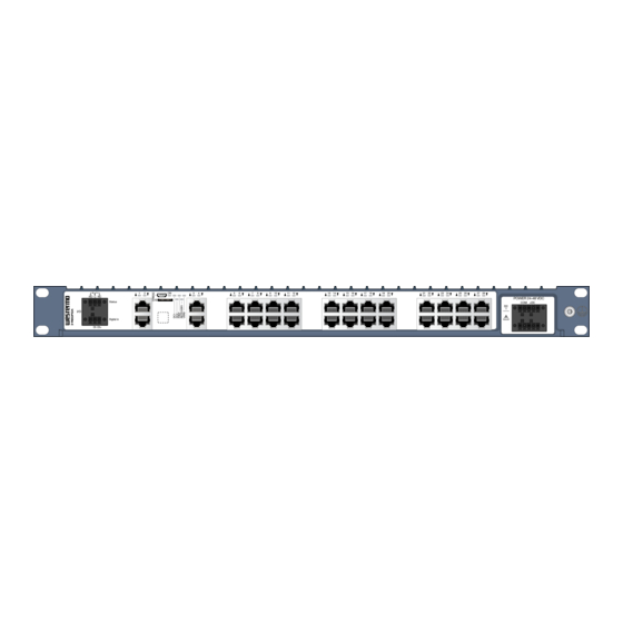
Page 12: Hardware Overview
Figure 5. Location of interface ports and LED indicators, illustrated by a RedFox-5528-F16G-T12G- 3.4. Connector Information 3.4.1. Power Input Illustration Position Product Direction Description marking +DC1 Input Supply voltage +DC2 Input Supply voltage -COM Input Common -COM Input Common Table 3. Power input LV and MV models RedFox 5528 Series... - Page 13 For screw connectors, make sure the screws are properly tightened, as well as routing the wires separately from other wires. For connectors with straps, fasten the cable as strain relief, as well as routing the wires separately. Figure 6. For HV models Figure 7. For MV models RedFox 5528 Series...
-
Page 14: I/O Connection
The console port can be used to connect to the CLI (Command Line Interface). The console connector is a micro USB cable that connects to a FTDI FT232R USB to serial converter internally. For drivers, refer to www.ftdichip.com and download the appropriate VCP driver RedFox 5528 Series... -
Page 15: Micro Sd
Figure 8. Insertion of micro SD card 3.4.5. SFP Transceivers The product supports UL and IEC certified transceivers only. See Westermo's modular transceivers datasheets 100 Mbit and 1 Gbit for supported SFP transceivers, which can be downloaded from the product support pages at www.westermo.com/support/product-... -
Page 16: Led Indicators
USR2 Configurable, see WeOS Management Guide TX/FX No link ports GREEN Link established GREEN Data traffic indication FLASH YELLOW Port alarm and no link. Or if FRNT or RSTP mode, port is blocked. Table 8. LED indicators RedFox 5528 Series... -
Page 17: Dimensions
3.6. Dimensions Dimensions are stated in mm. 482,4 7,2 (x4) Illustrated by RedFox-5528-T28G-HV. Figure 9. Dimensional drawing RedFox 5528 Series... -
Page 18: Installation
POWER 110-240 VAC / VDC Status N (-) L (+) AC/DC Digital in Figure 12. Earth connection 4.3. Cooling This product relies on convection cooling. To avoid obstruction of the airflow around the product, follow the spacing recommendations. RedFox 5528 Series... - Page 19 For wall mounting in an area without forced ventilation, a minimum spacing of 45 mm (1.75") above/below and 10 mm (0.4") left/right is recommended. For areas with forced ventilation, no minimal spacing is required as long as the temperature of the rear cooling plates does not exceed +85ºC (+185ºF). RedFox 5528 Series...
-
Page 20: Specifications
33 mA s at 110 VDC For all HV-models: 4 mA s at 240 VAC, 50 Hz 0.4 mA s at 110 VAC, 60 Hz 2 mA s at 240 VDC 0.1 mA s at 110 VDC RedFox 5528 Series... - Page 21 Tightening torque, terminal 0.22 - 0.25 Nm screw Terminal torque, screw flange 0.3 Nm Circuit type SELV ≤ 2.9 mA at 60 VDC Maximum voltage/current 60 VDC, I Voltage levels Logic one: >8 VDC Logic zero: <5 VDC RedFox 5528 Series...
- Page 22 Transmission range Up to 100 m with CAT5e cable or better Isolation All other ports Cabling Shielded cable CAT5e or better is recommended Conductive chassis 10/100/1000 Mbit/s ports are: RedFox-5528-(E-)T28G-LV/MV/HV: 1-28 RedFox-5528-(E-)F4G-24G-LV/MV/HV: 5-28 RedFox-5528-(E-)F16G-T12G-LV/MV/HV: 7-10, 15-18, 23-26 RedFox 5528 Series...
- Page 23 Up to 480 Mbps (high-speed mode) Circuit type SELV Maximum supply current 100 mA Connector USB Micro B connector in device mode Micro SD Electrical specification Secure Digital 2.0 Circuit type SELV Maximum supply current 100 mA Connector Micro SD connector RedFox 5528 Series...
-
Page 24: Type Tests And Environmental Conditions
(FCC Part 15 B, 30 MHz -25.5 GHz) Conducted RF CISPR 16-2-1 Power port LV and MV models: Class B emission HV models: Class A ANSI C63.4 LV and MV models: Class B HV models: Class A RedFox 5528 Series... - Page 25 HV models: 2000 VAC rms, 60 s DC) to all other ports I/O port to all other ports IEEE 802.3 Ethernet ports to 1500 VAC rms, 60 s all other ports Table 9. EMC and electrical conditions RedFox 5528 Series...
- Page 26 13.2-100 Hz, 1.0 grms, 150 minutes per (random) axis 5-2000 Hz, rms 2.3 m/s ,1.5h Shock Operational 30 g, 11 ms 60068-2-27 Enclosure EN 60950-1 Aluminum Fire enclosure Weight 3.8 kg Degree of protection EN 60529 Enclosure IP40 RedFox 5528 Series...
- Page 27 HV models: Class I equipment 61010-1 Location Indoor use For LV and MV models only Method 3, 21 days corresponds to Harsh Industrial Environment G3 which is defined in ANSI/ISA 17.04: 2015 Table 10. Environmental and mechanical conditions RedFox 5528 Series...
-
Page 28: Revision Notes
Change description Rev. G 2020-10 Westermo logo updated, illustrations throughout user guide updated with blue colour, 2.2 Safety information; warnings updated, 2.3 Care Recommendations; text updated, 2.5.1 Agency Approvals and Standards Compliance; table updated, 2.5.2 new chapter, 2.5.3 FCC Part 15.105 Class B Notice;... - Page 29 Revision Date Change description and Environmental Conditions updated - Surge updated, Corrosive gased added, Vibration updated, Radiated RF emission and Conducted RF emission updated Rev. A 2017-07 First issue of the user guide RedFox 5528 Series...
- Page 30 RedFox 5528 Series...
- Page 31 RedFox 5528 Series...
- Page 32 Westermo • SE-635 35 Stora Sundby, Sweden Tel +46 16 42 80 00 Fax +46 16 42 80 01 E-mail: info@westermo.com www.westermo.com 6641-22820 REV G 2020 10 Westermo Network Technologies AB, Sweden...
Need help?
Do you have a question about the RedFox 5528 Series and is the answer not in the manual?
Questions and answers