Table of Contents
Advertisement
Quick Links
Advertisement
Table of Contents

Related Manuals for Westermo RedFox 7528 Series


Summary of Contents for Westermo RedFox 7528 Series
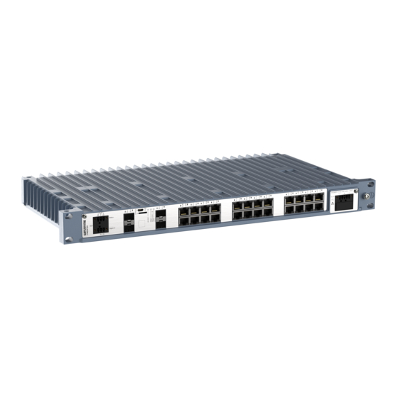
- Page 1 RedFox 7528 Series Industrial routing switches...
-
Page 2: Table Of Contents
4.2. Wall Mounting ..............16 4.3. Protective Earth Connection ..........16 4.4. Cooling ................16 5. Specifications ................18 5.1. Interface Specifications ............18 5.2. Type Tests and Environmental Conditions ......... 22 6. Revision Notes ................24 RedFox 7528 Series... -
Page 3: General Information
Westermo reserves the right to revise this document or withdraw it at any time without prior notice. Under no circumstances shall Westermo be responsible for any loss of data or income or any special, incidental, and consequential or indirect damages howsoever caused. -
Page 4: Safety And Regulations
No personal injury Minor damage to the order to avoid misuse of product the product, confusion or misunderstanding NOTICE Used for highlighting general, No personal injury Minor damage to the but important information product NOTE Table 1. Warning levels RedFox 7528 Series... -
Page 5: Safety Information
During installation, ensure a protective earthing conductor is first connected to the protective earthing terminal (only valid for metallic housings). Westermo recommends a cross-sectional area of at least 4 Upon removal of the product, ensure that the protective earthing conductor is disconnected last. - Page 6 ELECTROSTATIC DISCHARGE (ESD) Prevent electrostatic discharge damage to internal electronic parts by discharging your body to a grounding point (e.g. use a wrist strap). RedFox 7528 Series...
-
Page 7: Care Recommendations
If the product is not working properly, contact the place of purchase, the nearest Westermo distributor office or Westermo technical support. 2.4. Product Disposal This symbol means that the product shall not be treated as unsorted municipal waste when disposing of it. -
Page 8: Fcc Part 15.105 Class A Notice
CORROSIVE GASES If the product is placed in a corrosive environment, it is important that all unused connector sockets are protected with a suitable plug, in order to avoid corrosion attacks on the gold plated connector pins. Pending RedFox 7528 Series... -
Page 9: Simplified Declaration Of Conformity
2.5.5. Simplified Declaration of Conformity Hereby, Westermo declares that this product is in compliance with applicable EU directives and UK legislations. The full declaration of conformity and other detailed information is available at www.westermo.com/support/product-support. Figure 2. The European Conformity and the UK Conformity Assessment markings... -
Page 10: Product Description
Powered by WeOS, the Westermo network operating system the switches are flexible, feature rich as well as easy to install and configure. WeOS has been developed to allow cross-platform and future-proof solutions and can deliver resilient and flexible networks, e.g. -
Page 11: Hardware Overview
Figure 3. Location of interface ports and LED indicators', illustrated by a RedFox-7528-F4G10- F12G-T12G-LV 3.4. Connector Information 3.4.1. Power Input Illustration Product marking Direction Description +DC1 Input Supply voltage COM +DC +DC2 Input Supply voltage -COM Input Common -COM Input Common Table 3. Power input LV models RedFox 7528 Series... -
Page 12: I/O Connection
USB cable that connects to a FTDI FT232R USB to serial converter internally. For drivers, refer to www.ftdichip.com and download the appropriate VCP driver. 3.4.4. Micro SD To insert the micro SD card correctly, turn the gold plated pins upwards. Figure 4. Insertion of micro SD card RedFox 7528 Series... -
Page 13: Sfp Transceivers
3.4.5. SFP Transceivers The product supports UL and IEC certified transceivers only. See Westermo's modular transceivers datasheets for supported SFP and SFP+ transceivers, which can be downloaded from the product support pages at www.westermo.com/support/product- support. Each SFP slot can hold one SFP transceiver. See "Transceiver User Guide 6100-0000" for transceiver handling instructions, which also can be downloaded from the product support pages at www.westermo.com/support/product-support. -
Page 14: Led Indicators
USR2 Configurable, see WeOS5 User Guide TX/FX No link ports GREEN Link established GREEN Data traffic indication FLASH YELLOW Port alarm and no link. Or if FRNT or RSTP mode, port is blocked. Table 6. LED indicators RedFox 7528 Series... -
Page 15: Dimensions
3.6. Dimensions Dimensions are stated in mm. 482,4 DETAIL A SCALE 1 : 1 7,2 (x4) Figure 5. Dimensional drawing, illustrated by a RedFox-7528-F4G10-F12G-T12G-LV RedFox 7528 Series... -
Page 16: Mounting
25 26 27 28 NO C NC POWER 24-48 VDC Status Digital in Figure 8. Earth connection 4.4. Cooling This product relies on convection cooling. To avoid obstruction of the airflow around the product, follow the spacing recommendations. RedFox 7528 Series... - Page 17 For mounting in 19" apparatus cabinet without forced ventilation, a minimal spacing of 1U according to IEC 60297 or 45 mm (1.75") above/below is recommended. For wall mounting in an area without forced ventilation, a minimum spacing of 45 mm (1.75") above/below and 10 mm (0.4") left/right is recommended. RedFox 7528 Series...
-
Page 18: Specifications
Minimum temperature rating of the cable to be connected to the field wiring terminals is +77 °C Tightening torque, terminal 0.34 Nm screw Tightening torque, screw 0.34 Nm flange Shielded cable Not required Measured for 1 second at startup RedFox 7528 Series... - Page 19 Terminal torque, screw flange 0.3 Nm Circuit type SELV Type of switch Solid state, DC general use, DC Pilot duty Maximum withstand across 60 VDC (continous) open contacts Permissible current 80 mA (continous), 120 mA (short term 1 s.) RedFox 7528 Series...
- Page 20 1000 Mbit/s or 10 Gbit/s tranceiver supported Console port Electrical specification USB 2.0 device interface Data rate Up to 480 Mbps (high-speed mode) Circuit type SELV Maximum supply current 100 mA Connector USB Micro B connector in device mode RedFox 7528 Series...
- Page 21 Micro SD Electrical specification Secure Digital 2.0 Circuit type SELV Maximum supply current 100 mA Connector Micro SD connector RedFox 7528 Series...
-
Page 22: Type Tests And Environmental Conditions
EN/IEC/UL Power-, I/O- and 1500 VAC rms, 60 s 62368-1 Ethernet-ports to all other ports, incl. chassis IEEE 802.3 Ethernet-ports to 1500 VAC rms, 60 s all other ports, incl. chassis Table 7. EMC and electrical conditions RedFox 7528 Series... - Page 23 3.8 kg Degree of protection EN 60529 Enclosure IP40 Cooling Convection Location Indoor use Method 3, 21 days corresponds to Harsh Industrial Environment G3 which is defined in ANSI/ISA 17.04: 2015 Table 8. Environmental and mechanical conditions RedFox 7528 Series...
-
Page 24: Revision Notes
6. Revision Notes Revision Date Change description Rev. A 2022-05 First version of the user guide RedFox 7528 Series... - Page 25 Westermo • Metallverksgatan 6, SE-721 30 Västerås, Sweden Tel +46 16 42 80 00 Fax +46 16 42 80 01 E-mail: info@westermo.com www.westermo.com 6641-26001 REV A 2022 05 Westermo Network Technologies AB, Sweden...
Need help?
Do you have a question about the RedFox 7528 Series and is the answer not in the manual?
Questions and answers