
Subscribe to Our Youtube Channel
Related Manuals for Westermo RedFox Series


Summary of Contents for Westermo RedFox Series
- Page 1 User Guide 6641-22301 RedFox S E R I E S +DC1 +DC1 CON SOLE CON SOLE +DC2 +DC2 FRNT FRNT Industrial Routing Switch www.westermo.com...
-
Page 2: License Information
Under no circumstances shall Westermo be responsible for any loss of data or income or any special, incidental, and consequential or indirect damages howsoever caused. -
Page 3: Before Installation
Do not use or store the unit in dusty, dirty areas, connectors as well as other mechanical part may be damaged. If the unit is not working properly, contact the place of purchase, nearest Westermo dis- tributor office or Westermo Tech support. -
Page 4: Cleaning Of The Optical Connectors
Note. Fibre Optic Handling Fibre optic equipment needs special treatment. It is very sensitive to dust and dirt. If the fibre will be disconnected from the unit the protective hood on the transmitter/ receiver must be connected. The protective hood must be kept on during transportation. The fibre optic cable must also be handle the same way. -
Page 5: Declaration Of Conformity
Declaration of Conformity Westermo Teleindustri AB Declaration of conformity The manufacturer Westermo Teleindustri AB SE-640 40 Stora Sundby, Sweden Type of product Art no From serial no. RedFox, Industrial routing switch, all models 3641-3xxx 1000 is in conformity with the following EC directive(s). -
Page 6: Type Tests And Environmental Conditions
Type tests and environmental conditions Phenomena Test Description Test levels EN 61000-4-2 Enclosure contact ± 6 kV Enclosure air ± 8 kV RF field AM modulated IEC 61000-4-3 Enclosure 10 V/m 80% AM (1 kHz), 80 – 1000 MHz 20 V/m 80% AM (1 kHz), 800 – 1000 MHz 10 V/m 80% AM (1 kHz), 1400 –... -
Page 7: Functional Description
RedFox datasheet. For 'Getting Started' and management, please refer to the RedFox management guide. RedFox Industrial The listed RedFox have different combinations of interface modules, on the power CPU board two 100BaseTX Ethernet interfaces is available. Westermo Denomination Description article number 3641-3110... -
Page 8: Specification
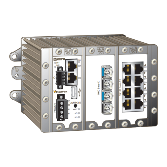
Housing Description The rack module is the aluminium housing that holds the interface modules. The housing is available in two sizes – a two-slot version and a three-slot version. Regardless of size and interface configuration, the slot on the left will always be occupied by the power and CPU module. - Page 9 The CPU board holds several interfaces. Two RJ-45 connectors with support for Ethernet 100BaseTX, a USB port for easy save/load system configuration and a console port for management through serial cable. Use SSH or the Westermo serial diagnostic cable (1211-2027) when connecting to the console port.
-
Page 10: Interface Specifications
Circuit type SELV Transmission range 15 m Isolation to All other except USB Galvanic connection to Connection 2.5 mm jack, use Westermo cable 1211-2027 Cable 1211-2027 Console port +DC1 CONSOLE +DC2 FRNT Connection to console port The console port can be used to connect to the CLI... - Page 11 Electrical specification USB 2.0 host interface Data rate Up to 12 Mbit/s (full-speed mode) Circuit type SELV Maximum supply current 500 mA Isolation to All other except Console Connection USB receptacle connector type A IO / Relay output 30 Ω Connect resistance Isolation to All other...
- Page 12 Position Direction* Description In/Out In/Out TD– In/Out – Not connected – Not connected In/Out RD– Not connected Not connected Shield In/Out Connected +DC1 to protective earth CONSOLE +DC2 FRNT Position Direction* Description VBUS In/Out D– In/Out Console Shield In/Out Connected (see more information to protective earth on page 10)
-
Page 13: Led Indicators Power/Cpu
LED indicators Power/CPU Status Description Unit has no power GREEN DC1 and DC2 power ok FRNT ok, if FRNT enabled No port alarm DC1 or DC2 power not ok FRNT ring broken, if FRNT enabled Port alarm FLASH* Connected to IP Configuration tool Unit disconnected +DC1 GREEN... -
Page 14: Interface Modules
Interface modules 8 Copper ports The interface module with eight copper ports has eight RJ-45 connectors supporting Ethernet 10/100BaseT/TX. All ports can, with category 5e cable or better, handle cable lengths up to 150 m (492 ft). Interfaces RFI-IM-01 Rated current 120 mA @ 24 VDC Electrical specification IEEE std 802.3. - Page 15 LED indicators Copper ports RFI-IM-01 Status Description Copper ports 1 – 8 No link GREEN Good link FLASH GREEN Data transmitted / received YELLOW Position Direction* Description In/Out In/Out TD– In/Out – Not connected – Not connected In/Out RD– – Not connected –...
- Page 16 F4G, 4 fibre ports The F4G interface module has four SFP slots supporting Ethernet 100/1000BaseFX/X. Each slot can hold one SFP transceiver for copper or fibre cable. Fibre transceiver dis- tances range from 550 m (0.34 mi) to 120 km (74,6 mi). For supported transceivers see section on SFP transceivers.
- Page 17 LED indicators on interface module F4G Status Description Fibre ports 1 – 4 No link GREEN Good link FLASH GREEN Data transmitted / received YELLOW Port larm and no link. Or Port is blocked, If RSTP/FRNT mode is activated. Position Direction* Description Receive port...
- Page 18 F4G-T4G The F4g-T4G interface module has four SFP slots supporting Ethernet 100/1000BaseFX/X and four RJ-45 connectors supporting Ethernet 10/100/1000BaseTX/T. Each SFP slot can hold one SFP transceiver for copper or fibre cable. Fibre transceiver distances range from 550 m (0.34 mi) to 120 km (74,6 mi). For supported transceivers see section on SFP transceivers.
- Page 19 Adding the values will give a total consumption of 760 mA @ 24 VDC. External power supply must be rated to meet the calculated current. Westermo recommends external power supply to be rated for a startup current which is at least twice the calculated in service consumption. In the example above an external power supply must be rated for at least 1520 mA for startup current.
-
Page 20: Supported Transceivers
1100-0142 XD-SM-LC50 1100-0148 CX-RJ-45 copper * Warning, to avoid damage on the receiver always use an optical attenuator if a loop back test is made with patch cables. Other transceivers will be available, please contact Westermo for more information. 6641-22301... - Page 21 1310 – Tx 1310 Rx 1550 Connector 2 Tx 1550 Rx 1310 Transceiver type LC Small Form Factor Pluggable (SFP) Laser class Class 1, IEC 825-1 Accessible Emission Limit (AEL) – * Other distances also available, please contact Westermo 6641-22301...
- Page 22 Snap on mounting, see figure. Note! For proper vibration and chock performance Westermo recommends standard top-hat DIN-rail TH 35-15 according to EN 60715. Removal Press down the support at the back of the unit using a screwdriver.
- Page 23 Configuration For getting started and management, please refer to the RedFox management guide found on the product CD or at the website, www.westermo.com/redfox Referring documents Type Description Document number Management Guide RedFox management guide 6642-32301...
- Page 24 6641-22301...
- Page 25 6641-22301...
- Page 26 6641-22301...
- Page 27 6641-22301...
- Page 28 Phone +65 6743 9801 • Fax +65 6745 0670 E-Mail: sales@westermo.co.uk E-Mail: sales@westermo.com.sg Westermo Data Communications GmbH Goethestraße 67, 68753 Waghäusel Tel.: +49(0)7254-95400-0 • Fax.:+49(0)7254-95400-9 E-Mail: info@westermo.de Westermo Teleindustri AB have distributors in several countries, contact us for further information.
Need help?
Do you have a question about the RedFox Series and is the answer not in the manual?
Questions and answers