Sign In
Upload
Download
Table of Contents
Contents
Add to my manuals
Delete from my manuals
Share
URL of this page:
HTML Link:
Bookmark this page
Add
Manual will be automatically added to "My Manuals"
Print this page
×
Bookmark added
×
Added to my manuals
Manuals
Brands
Siemens Manuals
Thermostat
RDG20 KN Series
Basic documentation
Siemens RDG20 KN Series Basic Documentation
Room thermostats, communicating and standalone
Hide thumbs
Also See for RDG20 KN Series
:
Basic documentation
(180 pages)
1
Table Of Contents
2
3
4
5
6
7
8
9
10
11
12
13
14
15
16
17
18
19
20
21
22
23
24
25
26
27
28
29
30
31
32
33
34
35
36
37
38
39
40
41
42
43
44
45
46
47
48
49
50
51
52
53
54
55
56
57
58
59
60
61
62
63
64
65
66
67
68
69
70
71
72
73
74
75
76
77
78
79
80
81
82
83
84
85
86
87
88
89
90
91
92
93
94
95
96
97
98
99
100
101
102
103
104
105
106
107
108
109
110
111
112
113
114
115
116
117
118
119
120
121
122
123
124
125
126
127
128
129
130
131
132
133
134
135
136
137
138
139
140
141
142
143
144
145
146
147
148
149
150
151
152
153
154
155
156
157
158
159
160
161
162
163
164
165
166
167
168
169
170
171
172
173
174
175
176
177
178
179
180
181
182
183
184
185
186
page
of
186
Go
/
186
Contents
Table of Contents
Bookmarks
Table of Contents
Table of Contents
About this Document
Revision History
Reference Documents
Before You Start
Trademarks
Copyright
Quality Assurance
Document User/Request to the Reader
Target Audience, Prerequisites
Glossary
Overview
Types
Functions
Accessories
Equipment Combinations
Recommended RDG Actuators and 6-Port Valves Combinations
Integration Via KNX Bus
Notes
Mounting and Installation
Commissioning
Operation
Remote Operation
Disposal
Cyber Security Disclaimer
Functions
Temperature Control
Operating Modes
Different Ways to Influence Operating Mode
Communication Examples
Room Temperature Setpoints
Description
Setting and Adjusting Setpoints
Application Overview
Applications for Fan Coil Systems
Applications for Universal Systems
Application for Heat Pump Systems
Power Supply Selection for RDG20
Additional Functions
Sensors and Changeover Functions
Presence Detector
Output Functions
Monitoring and Limiting Functions
User Operation / Indication
Humidity (RDG2
Scheduler
M/S, Manager/Subordinate (RDG2
Preventive Operation
NFC Communication
IAQ - CO2 Monitoring and Control (RDG2
Power Reserve Clock (RDG2
Control Sequences
Sequence Overview (Setting Via P001)
Application Mode
2-Pipe Fan Coil Unit
2-Pipe Fan Coil Unit with Electric Heater
2-Pipe Fan Coil Unit with Radiator or Floor Heating
2-Stage on 2-Pipe/4-Pipe Heating and Cooling
4-Pipe Fan Coil Unit
4-Pipe Fan Coil Unit with Electric Heater
Chilled/Heated Ceiling and Radiator Applications
Compressor Applications
Applications with External AQR Sensor or QMX Room Operator Unit (RDG2
Setpoints and Sequences
Control Outputs
Overview
Control Output Configuration for 6-Port Valve (P201)
Control Output Configuration (Setting Via DIP Switches 7/8 or Tool, and P201/P203/P204/P205)
Fan Control
Multifunctional Input, Digital Input
Handling System Faults
KNX Communications (RDG2
S-Mode
M/S, Manager/Subordinate Configuration in KNX S-Mode
LTE-Mode
Zone Addressing in LTE-Mode (with Synco)
M/S, Manager/Subordinate Configuration in LTE-Mode
Example of Heating and Cooling Demand Zones
Send Heartbeat and Receive Timeout
Startup
Heating and Cooling Demand
Fault and Alarms Function on KNX
Communication Objects (RDG2
Overview
Description of Communication Objects
Communication Objects (LTE-Mode) (RDG2
Control Parameters
Parameter Setting Via Local HMI
Setting/Downloading Parameter Via Tool (RDG2
Service Level Parameters
Expert Level Parameters with Diagnostics and Test
Supported Tools
Ets
Setting Parameters in ETS
ACS Tool
Setting Parameters in ACS
Operation and Monitoring with ACS
Operation and Monitoring with OZW772
PCT Go - Smartphone App
Commissioning Parameter Via PCT Go
Read Live Data Via PCT Go
Connection
Connection Terminals
Connection Diagrams
IAQ - CO2 Connection Diagrams (RDG2
Application Examples
Humidity Control
Relay Functions
Swap Function And/Or Fan in the 2Nd Stage
IAQ -CO2 Control (RDG2
Technical Data
Dimensions
Index
Advertisement
Quick Links
1
Mounting and Installation
Download this manual
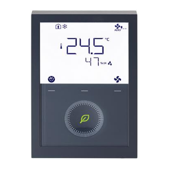
RDG20..KN.. & RDG26..KN..,
RDG200T, RDG260T
Room thermostats,
communicating and standalone
Basic Documentation
A6V11545892_en--_e
Smart Infrastructure
2023-06-20
Table of
Contents
Previous
Page
Next
Page
1
2
3
4
5
Advertisement
Table of Contents
Need help?
Do you have a question about the RDG20 KN Series and is the answer not in the manual?
Ask a question
Questions and answers
Related Manuals for Siemens RDG20 KN Series
Thermostat Siemens RDG20 KN Series Basic Documentation
Room thermostats with knx communications (180 pages)
Thermostat Siemens RDG200T Series Operating Instructions
(2 pages)
Thermostat Siemens RDG2 KN Series Operating Instructions
(2 pages)
Thermostat Siemens RDG2 KN Series Operating Instructions
(2 pages)
Thermostat Siemens RDG200KN Basic Documentation
Room thermostats with knx communications (150 pages)
Thermostat Siemens RDG200KN Mounting Instructions
(2 pages)
Thermostat Siemens RDG200T Basic Documentation
Room thermostats, communicating and standalone (186 pages)
Thermostat Siemens RDG400 Basic Documentation
Room thermostat with display, for vav (42 pages)
Thermostat Siemens RDG Series Application Manual
(28 pages)
Thermostat Siemens RDG100 Basic Documentation
Room thermostats with lcd for wall mounting (66 pages)
Thermostat Siemens RDG100 Documentation
Room thermostats with display, for fan coil units (60 pages)
Thermostat Siemens RDG100 Basic Documentation
With lcd for wall mounting (81 pages)
Thermostat Siemens RDG400KN Manual
(14 pages)
Thermostat Siemens RDG100KN Basic Documentation
With knx communications (132 pages)
Thermostat Siemens RDG100KN Instructions Manual
Room thermostat with knx communications (15 pages)
Thermostat Siemens RDG100KN Basic Documentation
Room thermostat with knx communications (86 pages)
This manual is also suitable for:
Rdg26 kn series
Rdg200t
Rdg260t
Table of Contents
Print
Rename the bookmark
Delete bookmark?
Delete from my manuals?
Login
Sign In
OR
Sign in with Facebook
Sign in with Google
Upload manual
Upload from disk
Upload from URL


Need help?
Do you have a question about the RDG20 KN Series and is the answer not in the manual?
Questions and answers