
Related Manuals for Belden Hirschmann RED25 Series


Summary of Contents for Belden Hirschmann RED25 Series
- Page 1 User Manual Installation Redundancy Switch RED25 Installation RED25 Technical support Release 01 02/2015 https://hirschmann-support.belden.eu.com...
- Page 2 The naming of copyrighted trademarks in this manual, even when not specially indicated, should not be taken to mean that these names may be considered as free in the sense of the trademark and tradename protection law and hence that they may be freely used by anyone. ©...
-
Page 3: Table Of Contents
Contents Safety instructions About this manual Description General description Device name and product code Device views Power supply Ethernet ports 1.5.1 10/100 Mbit/s twisted pair port 1.5.2 100 Mbit/s F/O port (optional) Display elements 1.6.1 Device state 1.6.2 Port state Management interfaces 1.7.1 V.24 interface (external management) 1.7.2 USB interface... - Page 4 Maintenance and service Disassembly Removing the device Removing an SFP transceiver (optional) Technical data Further Support Installation RED25 Release 01 02/2015...
-
Page 5: Safety Instructions
Safety instructions WARNING UNCONTROLLED MACHINE ACTIONS To avoid uncontrolled machine actions caused by data loss, configure all the data transmission devices individually. Before you start any machine which is controlled via data transmission, be sure to complete the configuration of all data transmission devices. Failure to follow these instructions can result in death, serious injury, or equipment damage. - Page 6 National and international safety regulations Verify that the electrical installation meets local or nationally applicable safety regulations. Grounding the device Grounding the device is by means of a separate ground connection on the device. Ground the device before connecting any other cables. ...
- Page 7 Relevance Requirements Relevant when the The following requirements are alternatively fulfilled: device is supplied via 1 Alternative 1 The voltage supply meets the requirements for a voltage input limited power source (LPS) as per EN 60950-1. Alternative 2 Relevant for North America: The voltage supply meets the requirements as per NEC Class 2 Alternative 3...
- Page 8 Relevance Requirements Relevant when the The following requirements are alternatively fulfilled: device is supplied via 2 Alternative 1 The total voltage supply meets the requirements voltage inputs for a limited power source (LPS) as per EN 60950-1. Alternative 2 Relevant for North America: The total voltage supply meets the requirements as per NEC Class 2.
- Page 9 Housing Only technicians authorized by the manufacturer are permitted to open the housing. Never insert pointed objects (narrow screwdrivers, wires, etc.) into the device or into the connection terminals for electric conductors. Do not touch the connection terminals. ...
- Page 10 LED or laser components LED or LASER components according to IEC 60825-1 (2007): CLASS 1 LASER PRODUCT CLASS 1 LED PRODUCT FCC note: This device complies with part 15 of the FCC rules. Operation is subject to the following two conditions: (1) this device may not cause harmful interference;...
-
Page 11: About This Manual
About this manual The “Installation” user manual contains a device description, safety instruc- tions, a description of the display, and the other information that you need to install the device. The following manuals are available as PDF files on the CD/DVD supplied: ... -
Page 12: Description
Description General description You can choose from between a wide range of variants. You have the option to set up your device individually based on different criteria: Types of connectors Temperature range Certifications Redundancy functions The RED25 devices are designed for the special requirements of industrial automation. -
Page 13: Device Name And Product Code
Device name and product code The device name corresponds to the product code. The product code is made up of characteristics with defined positions. The characteristic values stand for specific product properties. Item Characteristic Charac- Description teristic value 1 ... 3 Product Data rate Fast Ethernet switch... - Page 14 Item Characteristic Charac- Description teristic value 25 ... 26 Software level HiOS Layer 2 Standard 27 ... 31 Software version 04.1. Software-Version 04.1 XX.X. Current software version 32 ... 33 Bug fix Bugfix version 00 Current bugfix version Table 4: Device name and product code Application case Certificates and declarations...
- Page 15 Item Characteristic Description 1 ... 3 Product Data rate Fast Ethernet switch Hardware type Extended redundancy 7 ... 8 Number 4 × Fast Ethernet ports Fast Ethernet ports 9 ... 10 Number 0 × Gigabit Ethernet ports Gigabit Ethernet ports 11 ...
-
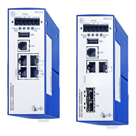
Page 16: Device Views
Device views 6 pin, screwable terminal block for redundant supply voltage and signal contact Terminal block connection On top of the device: Reset button (no function in the existing device version) LED display elements for device status USB interface V.24 interface Other ports 2 ×... -
Page 17: Power Supply
Locking gate for removing the device MAC address of device (label) Label area for IP address of device Table 7: Front view: on the left: Device variants RED25-04002T1TT-.DD..E2S..on the right: Device variants RED25-04002Z6TT-.DD..E2S..Power supply A 6-pin, screwable terminal block is available for the redundant supply to the device. -
Page 18: 100 Mbit/S F/O Port (Optional)
1.5.2 100 Mbit/s F/O port (optional) This port is an SFP slot. The 100 Mbit/s F/O port offers you the ability to connect network components according to the IEEE 802.3 100BASE-FX standard. This port supports: Full or half duplex mode Default setting: Full duplex Display elements After the working voltage is set up, the software starts and initializes itself. -
Page 19: Port State
Display Color Activity Meaning Ring Manager — None No redundancy configured Green Lights up Redundancy exists Flashes 1 time Device is reporting an incorrect configura- a period tion of the RM function Yellow Lights up No redundancy exists Storage medium —... -
Page 20: Usb Interface
The socket housing is electrically connected to the front panel of the device. The V.24 interface is electrically insulated from the working voltage. RJ11 RJ11 n.c. Figure 1: Pin assignment of the V.24 interface and the DB9 connector Note: You find the order number for the terminal cable, which is available as accessory, under “Accessories”... -
Page 21: Signal Contact
Signal contact The signal contact is a potential-free relay contact. The device allows you to perform remote diagnosis via the signal contact. In the process, the device signals events such as a line interruption. When an event occurs, the device opens the relay contact and interrupts the closed circuit. -
Page 22: Installation
Installation The devices have been developed for practical application in a harsh indus- trial environment. On delivery, the device is ready for operation. Perform the following steps to install and configure the device: Checking the package contents Installing and grounding the device ... -
Page 23: Installing The Device Onto The Din Rail
2.2.1 Installing the device onto the DIN rail Verify that the device maintains the minimum clearing in order to meet the climatic conditions: Verify that there is at least 4 in (10 cm) of space above and below the device. -
Page 24: Connecting The Power Supply And Signal Lines
Proceed as follows: Remove the protective cap from the SFP transceiver. Push the SFP transceiver with the lock closed into the socket until you hear it latch in. Connecting the power supply and signal lines WARNING ELECTRIC SHOCK Never insert pointed objects (narrow screwdrivers, wires, etc.) into the device or into the connection terminals for electric conductors. - Page 25 Supply voltage The supply voltage is only connected with the chassis via protective elements. You have the option of supplying the supply voltage redundantly, without load distribution. Both inputs are coupled with the supply connections via bridge rectifiers. With redundant power supply, the power supply unit with the higher output voltage supplies the device on its own.
-
Page 26: Operating The Device
Operating the device WARNING ELECTRIC SHOCK Connect only a supply voltage that corresponds to the type plate of your device. Failure to follow these instructions can result in death, serious injury, or equipment damage. Note: The torque for tightening the supply voltage terminal block on the device is 4.5 lb-in (0.51 Nm). -
Page 27: Making Basic Settings
Making basic settings Note: Two or more devices configured with the same IP address can cause unpredictable operation of your network. Install and maintain a process that assigns a unique IP address to every device in the network. The IP parameters must be entered when the device is installed for the first time. -
Page 28: Monitoring The Ambient Air Temperature
Monitoring the ambient air temperature Operate the device below the specified maximum ambient air temperature exclusively. See “General technical data” on page 32. The ambient air temperature is the temperature of the air at a distance of 2 in (5 cm) from the device. It depends on the installation conditions of the device, e.g. - Page 29 Maintenance and service When designing this device, Hirschmann largely avoided using high-wear parts. The parts subject to wear and tear are dimensioned to last longer than the lifetime of the product when it is operated normally. Operate this device according to the specifications. ...
- Page 30 Disassembly Removing the device Disconnect the data cables. Disable the supply voltage. Disconnect the terminal blocks. Disconnect the grounding. To remove the device from the DIN rail, you proceed as follows: Insert a screwdriver horizontally below the housing into the locking gate. ...
- Page 31 Removing an SFP transceiver (optional) Proceed as follows: Pull the SFP transceiver out of the socket by means of the opened lock. Close the SFP transceiver with the protective cap. Installation RED25 Release 01 02/2015...
- Page 32 Technical data General technical data Dimensions See “Dimension drawings” on page 34. W × H × D Weight RED25-04002T1TT... 300 g RED25-04002Z6TT... 320 g Power supply See “Requirements for connecting electrical conductors” on page 6. 2 voltage inputs for redundant power supply Nominal voltage AC 24 V Voltage range AC incl.
- Page 33 Climatic condi- Ambient air temperature −40 ºF ... +185 ºF (−40 ºC ... +85 ºC) tions during Humidity 10 % ... 95 % storage (non-condensing) Air pressure minimum 700 hPa (+9842 ft; +3000 m) maximum 1060 hPa (−1312 ft; −400 m) Signal contact See “Requirements for connecting electrical conductors”...
- Page 34 Dimension drawings 105,3 inch 4.15 1.81 0.37 Figure 2: Dimensions Installation RED25 Release 01 02/2015...
- Page 35 EMC and immunity Stability IEC 60068-2-6, test Fc Vibration 5 Hz ... 8.4 Hz with 0.14 in. (3.5 mm) ampli- tude 8.4 Hz ... 150 Hz with 1 g IEC 60068-2-27, test Ea Shock 15 g at 11 ms EMC interference emis- sion Radiated emission...
- Page 36 Network range Note: The line lengths specified for the transceivers apply for the respec- tive fiber data (fiber attenuation and BLP/dispersion). Product Wave Fiber System Example Fiber atten- BLP/ code length attenua- for F/O line uation dispersion M-FAST- tion length SFP-...
- Page 37 Power consumption/power output, order numbers The order numbers correspond to the product codes of the devices. See “Device name and product code” on page 13. Device name Maximum Power output power consumption RED25-04002T1TT... 24 BTU (IT)/h RED25-04002Z6TT... 31 BTU (IT)/h Scope of delivery ...
- Page 38 Fast Ethernet SFP transceiver Order number M-FAST SFP-SM/LC 943 866-001 M-FAST SFP-SM/LC EEC 943 946-001 M-FAST SFP-SM+/LC 943 867-001 M-FAST SFP-SM+/LC EEC 943 947-001 M-FAST SFP-LH/LC 943 868-001 M-FAST SFP-LH/LC EEC 943 948-001 Underlying technical standards Name EN 55022 Information technology equipment –...
- Page 39 Contact our support at https://hirschmann-support.belden.eu.com You can contact us in the EMEA region at Tel.: +49 (0)1805 14-1538 E-mail: hac.support@belden.com in the America region at Tel.: +1 (717) 217-2270 E-mail: inet-support.us@belden.com in the Asia-Pacific region at ...
Need help?
Do you have a question about the Hirschmann RED25 Series and is the answer not in the manual?
Questions and answers