
Subscribe to Our Youtube Channel
Related Manuals for Belden lumberg automation BEETLE


Summary of Contents for Belden lumberg automation BEETLE
- Page 1 User Manual Installation Single Pair Ethernet Lite Managed Switch BEETLE Technical Support Installation https://hirschmann-support.belden.com Release 01 - 05/2024...
- Page 2 You can get the latest version of this manual on the Internet at: http://doc.beldensolutions.com Please contact us if you have any detailed questions on installing and starting up the devices: Belden Deutschland GmbH Lumberg Automation™ Im Gewerbepark 2 D-58579 Schalksmühle Germany https://lumberg-automation-support.belden.com...
-
Page 3: About This Manual
About this manual The “Installation” user manual contains a device description, safety instructions, a description of the display, and the other information that you need to install the device. Documentation mentioned in the “Installation” user manual that is not supplied with your device as a printout can be found as PDF files for downloading on the Internet at: http://doc.beldensolutions.com... -
Page 4: Important Information
Important information Read these instructions carefully, and familiarize yourself with the device before trying to install, operate, or maintain it. The following notes may appear throughout this documentation or on the device. These notes warn of potential hazards or call attention to information that clarifies or simplifies a procedure. Installation Release 01 - 05/2024... -
Page 5: Warning Symbols
Warning symbols This is a general warning symbol. This symbol alerts you to potential personal injury hazards. Observe all safety notes that follow this symbol to avoid possible injury or death. If this symbol is displayed in addition to a safety instruction of the type “Danger” or “Warning”, it means that there is a danger of electric shock and failure to observe the instructions will inevitably result in in... - Page 6 NOTICE NOTICE provides information about procedures that do not involve the risk of injury. Installation Release 01 - 05/2024...
-
Page 7: Table Of Contents
Contents A bout this manual....................3 I mportant information................... 4 W arning symbols....................5 1. S afety instructions..................10 1.1. Q ualification requirements for personnel..........11 1.2. I ntended use..................11 1.3. I nstallation site requirements............... 12 1.4. - Page 8 3.4.3. S upport of PoDL................25 3.5. D isplay elements..................27 3.5.1. D evice status................27 3.5.2. P ort status..................28 4. I nstallation....................30 4.1. C hecking the package contents............30 4.2. M ounting the device................30 4.2.1.
- Page 9 8.8.1. E MC interference emission............45 8.8.2. E MC interference immunity............45 8.9. A ccessories..................46 8.10. S cope of delivery................47 8.11. O rder number..................47 8.12. U nderlying technical standards............47 9. G raphical User Interface (GUI)..............49 9.1.
-
Page 10: Safety Instructions
1 - Safety instructions 1. Safety instructions WARNING UNCONTROLLED MACHINE ACTIONS Failure to follow these instructions can result in death, serious injury, or equipment damage. To avoid uncontrolled machine actions caused by data loss, configure all the data transmission devices individually. Before you start any machine which is controlled via data transmission, be sure to complete the configuration of all data transmission devices. -
Page 11: Qualification Requirements For Personnel
1.1 - Qualification requirements 1 - Safety instructions for personnel 1.1. Qualification requirements for personnel Only allow qualified personnel to work on the device. Qualified personnel have the following characteristics: • Qualified personnel are properly trained. Training as well as practical knowledge and experience make up their qualifications. -
Page 12: Installation Site Requirements
1.3 - Installation site 1 - Safety instructions requirements 1.3. Installation site requirements WARNING FIRE HAZARD Failure to follow these instructions can result in death, serious injury, or equipment damage. If you connect the device to a power supply that does NOT meet the requirements for Limited Power Source, NEC Class 2 or PS2 according to IEC/EN 62368-1 and is NOT limited to 100 W output power, the device must be... -
Page 13: Strain Relief
1 - Safety instructions 1.5 - Strain relief • Never insert pointed objects (narrow screwdrivers, wires, etc.) into the device or into the connection terminals for electric conductors. Do not touch the connection terminals. • Keep the ventilation slits free to ensure good air circulation. •... -
Page 14: General Requirements For Connecting The Supply Voltage
1 - Safety instructions 1.6 - Electrical connections • The electrical wires are voltage-free. • The device is grounded via the designated ground connection(s). • The cross-section of the ground conductor is the same size or larger than the cross-section of the power supply cables. •... -
Page 15: Specific Requirements For Connecting The Supply Voltage
1 - Safety instructions 1.6 - Electrical connections • The supply voltage corresponds to the voltage specified on the type plate of the device. • The power supply cable is suitable for the required voltage, current, and physical load. • The cross-section of the ground conductor is the same size as or larger than the cross-section of the power supply cables. -
Page 16: Recycling Note
1 - Safety instructions 1.7 - Recycling note • The power supply complies with the requirements for a safety extra-low voltage (SELV) according to IEC 60950-1 or ES1 according to IEC/EN 62368-1. • Supply with DC voltage: A back-up fuse suitable for DC voltage is located in the plus conductor of the pow er supply. -
Page 17: Approvals
2 - Approvals 2. Approvals 2.1. CE marking The labeled devices comply with the regulations contained in the following European directive(s): • 2011/65/EU and 2015/863/EU (RoHS) Directive of the European Parliament and of the Council on the restriction of the use of certain hazardous substances in electrical and electronic equipment. -
Page 18: Ukca Marking
Electromagnetic Compatibility Regulations The UKCA conformity declaration will be available to the relevant authorities at the following address: Belden UK Ltd. 1 The Technology Centre, Station Road Framlingham, IP13 9EZ, United Kingdom You find the UKCA conformity declaration as PDF file for downloading on the Internet at: http://doc.beldensolutions.com/certificates.html... -
Page 19: Description
The device allows you to set up switched Industrial Ethernet networks according to the standard IEEE 802.3. You have numerous options of combining the device characteristics. You can determine the possible combinations using the configurator which is available in the Belden Online Catalog on the web page of the https://catalog.belden.com device. - Page 20 3.1 - Device name and product 3 - Description code Table 1. Device name and product code (continued) Characteristic Item Characteristic Description value Twisted pair ports: standard Fast Ethernet Gigabit Ethernet (GE) 17... 20 Twisted pair ports: number 02TX 2 x twisted pair RJ45 copper ports 03TX 3 x twisted pair RJ45 copper ports Temperature range...
-
Page 21: Device Views
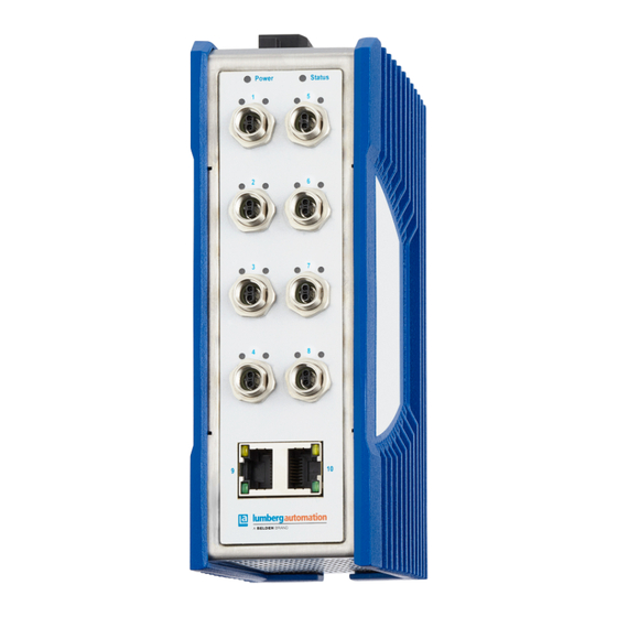
3 - Description 3.2 - Device views 3.2. Device views 3.2.1. Front view Power Status Front view of device BTL-1L516W208T1202TXSZ9HHHH Item Description 6-pin, pluggable terminal block for power supply LED display elements for device status 8 × M8 Single Pair Ethernet ports 10BASE-T1L downlink 2 ×... -
Page 22: Power Supply
3 - Description 3.3 - Power supply 3.3. Power supply The following options for power supply are available: 3.3.1. Supply voltage range 18 V DC ... 32 V DC Corresponds in the product code with the supply voltage characteristic value HH (items 26 ... 27). • 12 V DC ... 24 V DC with 6-pin terminal block with screws: Corresponds in the product code with the customer-specific version characteristic value HH (items 24 ... 25). -
Page 23: Twisted Pair Port 10/100 Mbit/S
3 - Description 3.4 - Ethernet ports The 10 Mbit/s SPE (Single Pair Ethernet) port allows you to connect network components according to the IEEE 802.3 10BASE-T1L standard. This port supports: • Auto-Negotiation • Autopolarity • PoDL (Power over Data Line) •... - Page 24 3 - Description 3.4 - Ethernet ports • Auto-Negotiation • Autopolarity • Auto-Crossover (if Auto-Negotiation is enabled) • 100 Mbit/s half duplex mode, 100 Mbit/s full duplex mode • 10 Mbit/s half duplex mode, 10 Mbit/s full duplex mode Delivery state: Auto-Negotiation enabled The pin assignment corresponds to MDI. Pin assignments Table 3.
-
Page 25: Support Of Podl
3 - Description 3.4 - Ethernet ports 3.4.3. Support of PoDL BEETLE supports Power over Data Line (PoDL) in accordance with IEEE 802.3 clause 104 including additions from IEEE 802.3cg. PoDL-capable Ethernet ports are designed as M8 sockets. See Device views on page The PoDL ports allow the connection and remote supply of, for example, sensors, scanners and Web cams. - Page 26 3 - Description 3.4 - Ethernet ports Technical standard Description IEEE 802.3, clause 104 PoDL max. power provided from the Power Source Equipment (PSE) Class 10/11/12 with 1.85 W/4.8 W/12.63 W at a voltage range between 20 V DC… 30 V DC Installation Release 01 - 05/2024...
-
Page 27: Display Elements
3 - Description 3.5 - Display elements 3.5. Display elements After the supply voltage is switched on, the device performs a self-test. During this process, various LEDs light up. 3.5.1. Device status This LED provides information about conditions which affect the operation of the whole device. -
Page 28: Port Status
3 - Description 3.5 - Display elements Table 5. Status LED: Color, activity and meaning (continued) Color Activity Meaning Configuration failed Firmware update in progress green solid Device is ready for operation 3.5.2. Port status These LEDs display port-related information. Ports 1 ... - Page 29 3 - Description 3.5 - Display elements Table 7. M8 port LED P (PoDL): Color, activity and meaning Color Activity Meaning none none Power off yellow lights up Power fault (e.g. voltage out of range) green lights up Power on (PoDL or Hybrid power) Ports 9 + 10 Power Status...
-
Page 30: Installation
4 - Installation 4. Installation The devices have been developed for practical application in a harsh industrial environment. On delivery, the device is ready for operation. Perform the following steps to install and configure the device: • Checking the package contents on page 30 •... -
Page 31: Mounting The Device Onto The Din Rail
4 - Installation 4.2 - Mounting the device 4.2.1. Mounting the device onto the DIN rail The device is designed to be mounted on a 35 mm (1.38 in) DIN rail in accordance with DIN EN 60715. Perform the following work steps: • Slide the upper snap-in guide of the device onto the DIN rail. •... -
Page 32: Mounting On A Flat Surface
4 - Installation 4.2 - Mounting the device 4.2.2. Mounting on a flat surface inch 57,5 2.26 1.65 24,25 0.95 35,75 1.41 inch 87,5 3.44 2.83 54,25 2.14 65,75 2.59 2 models of wall mounting plates are available: Accessories on page 46 Perform the following work steps: •... -
Page 33: Grounding The Device
4 - Installation 4.3 - Grounding the device • Mount the device on the wall mounting plate. Insert the upper snap-in guide of the device into the rail and press it down against the rail until it snaps into place. 4.3. -
Page 34: C Onnecting The Supply Voltage
4.4 - Connecting the supply 4 - Installation voltage 4.4. Connecting the supply voltage WARNING ELECTRIC SHOCK Failure to follow this instruction can result in death, serious injury, or equipment damage. Exclusively connect a supply voltage that corresponds to the type plate of your device. Never insert sharp objects (small screwdrivers, wires, etc.) into the connection terminals for the supply voltage, and do not touch the terminals. -
Page 35: Connecting The 6-Pin Terminal Block With Screws
4.4 - Connecting the supply 4 - Installation voltage Table 9. Type and specification of the supply voltage and pin assignment on the device (continued) Pin assignment +24 V DC (P1) Plus terminal of the supply voltage P1 – Not connected 0 V DC Minus terminal of the supply voltage P1 0 V DC Minus terminal of the supply voltage P2... -
Page 36: Operating The Device
4 - Installation 4.5 - Operating the device Perform the following work steps: • Verify the required conditions for connecting the voltage supply. Safety instructions on page 10 • Remove the terminal connector from the device. • Connect the wires according to the pin assignment on the device with the clamps. - Page 37 4 - Installation 4.6 - Connecting data cables • Keep the cable length to a minimum, but in any case within the maximum distances specified in the applicable standards. • When using copper cables, provide a sufficient separation between the power supply cables and the data cables.
-
Page 38: Monitoring Ambient Conditions
5 - Monitoring ambient conditions 5. Monitoring ambient conditions 5.1. Monitoring the ambient air temperature Operate the device below the specified maximum ambient air temperature exclusively. Climatic conditions during operation on page The ambient air temperature is the temperature of the air at a distance of 5 cm (2 in) from the device. -
Page 39: Maintenance And Service
6 - Maintenance and service 6. Maintenance and service • When designing this device, Lumberg Automation™ largely avoided using high-wear parts. The parts subject to wear and tear are dimensioned to last longer than the lifetime of the product when it is operated normally. -
Page 40: Disassembly
7 - Disassembly 7. Disassembly 7.1. Removing the device WARNING ELECTRIC SHOCK Failure to follow these instructions can result in death, serious injury, or equipment damage. Disconnect the grounding only after disconnecting all other cables. WARNING ELECTRIC SHOCK Failure to follow this instruction can result in death, serious injury, or equipment damage. - Page 41 7 - Disassembly 7.1 - Removing the device Installation Release 01 - 05/2024...
-
Page 42: Technical Data
8 - Technical data 8. Technical data 8.1. General data Dimensions BEETLE Dimension drawings W × H × D on page 43 Weight BTL-1L516W208T1202TXSZ9HHHH 1016 g (35.84 oz) Power supply Configuration: standard Rated voltage (operation) 24 V DC (characteristic value HH, Voltage range incl. maxi 18 V DC ... -
Page 43: Dimension Drawings
8 - Technical data 8.4 - Dimension drawings 8.4. Dimension drawings 8.4.1. Dimension drawings 0.82 Installation Release 01 - 05/2024... -
Page 44: Climatic Conditions During Operation
8.5 - Climatic conditions during 8 - Technical data operation 8.5. Climatic conditions during operation Table 11. Climatic conditions during operation Climatic conditions during operation Ambient air temperature -10 °C ... +60 °C (+14 °F ... +140 °F) Derating Humidity 1 % ... 95 % (non-condensing) Air pressure min. 700 hPa (+3000 m ASL; +9842 ft ASL) 8.6. -
Page 45: Electromagnetic Compatibility (Emc)
8.8 - Electromagnetic 8 - Technical data compatibility (EMC) 8.8. Electromagnetic compatibility (EMC) Note: U se shielded data cables according to IEC 61156-13, IEC 61156-14 and ISO/IEC 11801. Note: U se shielded data cables according to IEC 61156-13, IEC 61156-14 and ISO/IEC 11801. 8.8.1. EMC interference emission Table 14. -
Page 46: Accessories
EN 61000-4-6 150 kHz ... 80 MHz 10 V 8.9. Accessories You find more information on available accessories in the Belden Online Catalog, https://catalog.belden.com Note that products recommended as accessories may have different characteristics to those of the device, which may limit the application range of the overall system. -
Page 47: Scope Of Delivery
You will find out whether your device has other shipping approvals on the Lumberg Automation™ website at: https:// in the product information. belden.com Table 18. List of the technical standards EN 55032 Electromagnetic compatibility of multimedia equipment – Emission Require... - Page 48 8.12 - Underlying technical 8 - Technical data standards Table 18. List of the technical standards (continued) EN 61000-3-3 Electromagnetic compatibility (EMC) – Part 3-3: Threshold values – limitation of voltage changes, voltage fluctuations and flickering in public low power supply networks for devices with a rated current ≤16 A per conductor that are not sub ject to any special connection condition EN 61000-6-2 Electromagnetic compatibility (EMC) –...
-
Page 49: Graphical User Interface (Gui)
9 - Graphical User Interface (GUI) 9. Graphical User Interface (GUI) This section will cover the following topics: • Accessing the Graphical User Interface (GUI): Find instructions on how to access the web-based interface. See Access on page • User Management: Learn the ins and outs of user management and authentication processes to help ensure secure access. - Page 50 9 - Graphical User Interface 9.1 - Access (GUI) • Validate that the device is connected to the power supply and to the network. Confirm that the device IP address is obtained and known as this is a condition to have access to the device's GUI. •...
-
Page 51: User Management
9 - Graphical User Interface 9.2 - User Management (GUI) • Once the Username and password credentials have been provided and the login process to the GUI is completed, the following GUI portal will show up: Note: In case a user is logged in without having the administrator role, the following read-only GUI will show up: 9.2. - Page 52 9 - Graphical User Interface 9.2 - User Management (GUI) Important: In order to proceed with user management functionality, users with administrative privileges should be logged in to the Graphical User Interface. An administrator user should follow the next steps in order to add a new GUI user: •...
- Page 53 9 - Graphical User Interface 9.2 - User Management (GUI) • In order to add a new user to the device's GUI, click on the button "Add User" below the table "Users": • By clicking on the button "Add User", the following form "Add User" will be displayed.
-
Page 54: Data And Monitoring
9 - Graphical User Interface 9.3 - Data and Monitoring (GUI) Guest: Allows users a read-only access to the device functionalities. These users can only observe device status information, system information, contact information and licensing information. OPCUA: Allows users a read-only access to the device functionalities except full access to the OPC UA server configuration functionality. -
Page 55: System
9 - Graphical User Interface 9.3 - Data and Monitoring (GUI) The tab "Status" contains three informative sections: • Device Overview: This section contains a graphical representation of the device. • Device Information: The following section provides information about current firmware version and current device status. •... - Page 56 9 - Graphical User Interface 9.3 - Data and Monitoring (GUI) The "System" tab contains the following general information: Firmware This section contains the actual firmware version. Device This informative section contains the following information: Installation Release 01 - 05/2024...
- Page 57 9 - Graphical User Interface 9.3 - Data and Monitoring (GUI) • Name: Represents the assigned device name. This field can be modified and changed by users with administrative privileges. In order to update the device name, click on the edit icon " " next to the current device name, provide a new device name and save all changes.
-
Page 58: Podl
9 - Graphical User Interface 9.3 - Data and Monitoring (GUI) Network In this part of the device general information section the current device network parameters are displayed. The following parameters are included in this section: • Device IP address: This parameter represents the actual IP address of the device. - Page 59 9 - Graphical User Interface 9.3 - Data and Monitoring (GUI) This page provides users with administrative privileges to monitor and configure Power over Data Line functionality per each single-pair ethernet port available on the device. Installation Release 01 - 05/2024...
-
Page 60: Logging
9 - Graphical User Interface 9.3 - Data and Monitoring (GUI) • Port Status: This graphical indicator demonstrates real-time status of the PoDL functionality on the specific single-pair ethernet (SPE) port. This indicator may include one of the following options: •... - Page 61 9 - Graphical User Interface 9.3 - Data and Monitoring (GUI) Audit Log This section records every interaction within the GUI, providing a transparent and accountable trail of user actions. Each record in the audit log table represents a unique event generated by user action. The following information is presented in the audit log record: •...
-
Page 62: Contact
9 - Graphical User Interface 9.3 - Data and Monitoring (GUI) Note: The Audit logging table can only display the latest 100 event records. Use the button "Download" to download the whole audit log from the device. 9.3.5. Contact The "Contact" page contains manufacturer information such as: Company name, Company address and Postal code, Country, and Web site address. -
Page 63: Licenses
9 - Graphical User Interface 9.4 - Configuration Settings (GUI) 9.3.6. Licenses This section provides in-depth details about the open-source software components utilised in constructing the firmware and applications for the Lite Managed Switch BEETLE. The licenses information is organized in a table providing the following data: •... -
Page 64: P Orts
9 - Graphical User Interface 9.4 - Configuration Settings (GUI) The Configuration Settings encompass the following potential device configurations: • Port settings: Ports on page 64 • RSTP settings: RSTP on page 67 • ACL settings: ACL on page 71 •... - Page 65 9 - Graphical User Interface 9.4 - Configuration Settings (GUI) Table 19. Port parameters Web interface Parameter Description Port: Represents the port enumerator which ranges from 1 to 10. Port Type: Indicates the type of the selected port. There are two options: SPE for a single-pair ethernet port or MPE for a multi-pair ethernet port.
- Page 66 9 - Graphical User Interface 9.4 - Configuration Settings (GUI) 9.4.1.1. SPE ports Single-Pair Ethernet ports support the following two additional configuration options: Port Signaling Refers to the configuration parameter which determines how the SPE port communicates, the voltage levels involved in the signaling process, and whether the port automatically adjusts its settings or operates with predefined voltage levels as following: •...
-
Page 67: Rstp
9 - Graphical User Interface 9.4 - Configuration Settings (GUI) In order to save the port settings, the administrator should click on the button "Save" at the right bottom part of the RSTP configuration settings form. 9.4.2. RSTP RSTP configuration settings specify parameters that control the behavior of RSTP on individual switch ports. - Page 68 9 - Graphical User Interface 9.4 - Configuration Settings (GUI) The RSTP configuration settings contain the following configuration parameters: Installation Release 01 - 05/2024...
- Page 69 9 - Graphical User Interface 9.4 - Configuration Settings (GUI) • RSTP State: This property enables or disables RSTP functionality for the device. If this configuration is disabled, no RSTP configuration parameters are displayed. • Bridge ID: The Bridge ID is a combination of the switch's priority value and its MAC address.
- Page 70 9 - Graphical User Interface 9.4 - Configuration Settings (GUI) The form "RSTP Port Settings" includes the following RSTP port configuration parameters: • Port: This read-only parameter identifies the port name. • Port RSTP Status: This property is used in order to enable or disable the RSTP functionality on a specific port.
-
Page 71: A Cl
9 - Graphical User Interface 9.4 - Configuration Settings (GUI) 9.4.3. ACL Access Control Lists (ACLs) serve as crucial components in network security by providing a method to selectively permit or deny traffic based on specified criteria. In essence, ACLs function as traffic filters, allowing network administrators to define rules that control which packets are allowed or blocked at the device interface. - Page 72 9 - Graphical User Interface 9.4 - Configuration Settings (GUI) • ACL Rule Name: This parameter represents a unique ACL rule name. The ACL name may contain any alphanumeric characters. • Source MAC: This field Source MAC address refers to the MAC address of the network interface card (NIC) in the device that is transmitting a network frame or packet into the network.
- Page 73 9 - Graphical User Interface 9.4 - Configuration Settings (GUI) The table "Access Control Lists Rules" includes all assigned rules in the system. Each row in the table represents an ACL rule. The rule can be removed by administrative users by clicking on the icon " "as it is shown in the following example: Moreover, administrators have the flexibility to modify the order in which...
-
Page 74: L Ldp
9 - Graphical User Interface 9.4 - Configuration Settings (GUI) 9.4.4. LLDP LLDP (Link Layer Discovery Protocol) in a device is a protocol that facilitates the automatic discovery of neighbouring network devices, providing information such as device type, port identification, and capabilities. This protocol enhances network visibility, simplifies device management, and promotes interoperability by allowing devices to dynamically share key details about their presence and configuration. - Page 75 9 - Graphical User Interface 9.4 - Configuration Settings (GUI) The "VLAN" page consists of two sub-pages, "VLAN Ports Settings" and "VLANs Settings". 9.4.5.1. VLAN Ports Settings By default, upon opening the VLAN configuration settings page, the sub- page "VLAN Ports Settings" is displayed. This section provides details regarding VLAN-related configurations for each of the device ports.
- Page 76 9 - Graphical User Interface 9.4 - Configuration Settings (GUI) The "VLAN Ports Settings" form contains the following configurable parameters: • Port Number: Designates the number of the port for which the VLAN settings will be modified. • Ingress Filtering: This parameter enables or disables the ingress filtering functionality that controls how incoming traffic is handled within a specific port.
- Page 77 9 - Graphical User Interface 9.4 - Configuration Settings (GUI) 'Forbidden' → Frames with this VLAN tag are explicitly forbidden on the switch port. If a frame with the specified VLAN tag arrives, it is typically dropped or ignored. 'Tagged' → In mode 'Tagged', the switch port accepts frames with VLAN tags.
- Page 78 9 - Graphical User Interface 9.4 - Configuration Settings (GUI) • VLAN Settings: Located on the left-upper side of the "VLANs Settings" sub-page, representing general VLAN settings. This section contains the following informative and configurable parameters: 'VLAN State' → This property enables or disables VLAN functionality for the device.Once this configuration is disabled no VLAN settings configuration parameters are displayed.
- Page 79 9 - Graphical User Interface 9.4 - Configuration Settings (GUI) • Management VLAN: Located on the right-upper side of the sub-page "VLANs Settings", representing the "Management VLAN" settings configuration. This section contains the following configurable parameters: 'VLAN ID' → This parameter is used in networking to identify and separate broadcast domains within a larger network.
-
Page 80: Q Os
9 - Graphical User Interface 9.4 - Configuration Settings (GUI) In order to save VLAN settings, the administrator should click on the button "Save" at the top of the VLAN configuration settings page. 9.4.6. QoS Quality of Service (QoS) implementation involves the utilization of queues, which are instrumental for organizing and prioritizing network traffic. - Page 81 9 - Graphical User Interface 9.4 - Configuration Settings (GUI) • Port: This parameter allows the administrator to select an appropriate port to which a new Qos queue will be assigned. There are 10 network ports implemented in BEETLE devices. •...
- Page 82 9 - Graphical User Interface 9.4 - Configuration Settings (GUI) • Queue Priority: This parameter refers to the priority assigned to a specific queue in the egress (outgoing) direction. Different queues are often used to prioritize or categorize traffic based on their characteristics, and assigning priority helps determine the order in which packets are processed and transmitted.
-
Page 83: M Ac Table
9 - Graphical User Interface 9.4 - Configuration Settings (GUI) On the right-hand side of the "QoS" page there is the table "QoS Queues" which is used to show and summarize every queue assigned in the system. There is a filtering option to help users to filter relevant network port queues by providing the port number. - Page 84 9 - Graphical User Interface 9.4 - Configuration Settings (GUI) • Static MAC Addresses: These are manually configured MAC addresses associated with specific devices on the network. Static MAC addresses are predetermined and remain fixed, providing a means of controlling access to the network based on known device addresses.
- Page 85 9 - Graphical User Interface 9.4 - Configuration Settings (GUI) On the left-hand side of the MAC Addresses Table page there is the form "MAC Parameters" that is used in order to add a new MAC address or update a specific one from one of the MAC tables. This form contains the following parameters: Installation Release 01 - 05/2024...
- Page 86 9 - Graphical User Interface 9.4 - Configuration Settings (GUI) • MAC Type: This parameter designates the classification of the MAC address record, specifying whether it will be incorporated as a "Static" or "Multicast" MAC address record. Depending on this parameter, the MAC address configuration is then added or updated in the respective table.
-
Page 87: P Odl
9 - Graphical User Interface 9.4 - Configuration Settings (GUI) • Ports: Specific network ports or interfaces associated with individual MAC addresses. This functionality is integral to network switches and devices as it establishes the correspondence between MAC addresses and their respective physical or virtual ports. For “Static” MAC addresses there is only a single port that might be assigned and for “Multicast”... - Page 88 9 - Graphical User Interface 9.4 - Configuration Settings (GUI) • Available Power Budget: This property provided by the device firmware and represents the maximum amount of electrical power that can be allocated or supplied for PoDL functionality over data lines. The value can not be overwritten and is represented in watts.
-
Page 89: I P
9 - Graphical User Interface 9.4 - Configuration Settings (GUI) 9.4.9. IP There are two different methods for assigning IP addresses to the devices on a network: • Static IP Configuration: With static IP configuration, an administrator manually assigns a specific IP address to a device. The assigned IP address remains constant, providing stability for devices that need a fixed, unchanging address. - Page 90 9 - Graphical User Interface 9.4 - Configuration Settings (GUI) This form contains two configuration options, "Static" and "DHCP". Once the option "Static" is selected, there are three parameters that need to be provided: • IP Address: Users need to manually assign an IP address following the standard IP address format.
-
Page 91: O Pc Ua
9 - Graphical User Interface 9.4 - Configuration Settings (GUI) 9.4.10. OPC UA Open Platform Communications Unified Architecture (OPC UA) is a standardized cross-platform communication protocol designed for industrial automation and the Industrial Internet of Things (IIoT). It serves as a foundation for secure and reliable data exchange between various devices and systems within industrial environments. - Page 92 9 - Graphical User Interface 9.4 - Configuration Settings (GUI) • Port: This parameter specifies the network port number on which the OPC UA server will listen for incoming connections. In this case, it is set to '4841'. • Anonymous Login: This option determines whether the OPC UA server allows connections without explicit user authentication.
-
Page 93: Firmware Update
9 - Graphical User Interface 9.5 - Firmware Update (GUI) 9.5. Firmware Update The "Firmware Update" functionality within the Graphical User Interface of a device empowers users to enhance and optimize their device's performance, security, and feature set by applying the latest firmware releases provided by the device manufacturer. - Page 94 9 - Graphical User Interface 9.5 - Firmware Update (GUI) • 4. Click on the button "Upload" in order to upload the desired firmware file into the system. The file will be uploaded and a process bar will be displayed: •...
-
Page 95: Restore Default Configuration
9 - Graphical User Interface 9.6 - Restore Default (GUI) Configuration • 7. Once the firmware update process is completed, a device reboot will be required and is requested as following: • 8. Click the button "Reboot" in order to reboot the device and complete the firmware update process. - Page 96 9 - Graphical User Interface 9.6 - Restore Default (GUI) Configuration • 1. Select the option "System" in the main menu and scroll down to the bottom part of the displayed page: There are two restore options available: 'Reset configuration to factory defaults' → This option resets the device configuration settings to the factory defaults.
- Page 97 9 - Graphical User Interface 9.6 - Restore Default (GUI) Configuration • 4. By clicking "Ok", the restore process will start and upon its completion the following message will be displayed: • 5. In order to reset the device to the factory defaults, check the lower confirmation checkbox under "Reset device to factory defaults": Installation Release 01 - 05/2024...
- Page 98 9 - Graphical User Interface 9.6 - Restore Default (GUI) Configuration • 6. Click the button "Factory Reset" to start the device resetting process. The confirmation dialog will be displayed: • 7. By clicking "Ok", the restore process will start and upon its completion the following message will be displayed: Installation Release 01 - 05/2024...
-
Page 99: Further Support
For technical questions, please contact any Hirschmann dealer in your area or Hirschmann directly. You find the addresses of our partners on the Internet at: https://belden.com A list of local telephone numbers and email addresses for technical support directly from Lumberg Automation™ is available at: https://lumberg-automation-support.belden.com... - Page 100 Installation Release 01 - 05/2024...
Need help?
Do you have a question about the lumberg automation BEETLE and is the answer not in the manual?
Questions and answers