
Related Manuals for Belden HIRSCHMANN BRS20


Summary of Contents for Belden HIRSCHMANN BRS20
- Page 1 User Manual Installation Industrial Ethernet Industrial Ethernet BOBCAT Rail Switch BRS20/22/30/32/40/42/50/52 Installation BRS20/22/30/32/40/42/50/52 Technical support Release 12 01/2022 https://hirschmann-support.belden.com...
- Page 2 The naming of copyrighted trademarks in this manual, even when not specially indicated, should not be taken to mean that these names may be considered as free in the sense of the trademark and tradename protection law and hence that they may be freely used by anyone. ©...
-
Page 3: Table Of Contents
Contents Important information Safety instructions About this manual Description General device description Device name and product code Device views 1.3.1 Front view 1.3.2 Rear view Power supply 1.4.1 Supply voltage with characteristic value T 1.4.2 Supply voltage with characteristic value F 1.4.3 Supply voltage with characteristic value U 1.4.4 Supply voltage with characteristic value P Ethernet ports... - Page 4 Installation Checking the package contents Installing and grounding the device 2.2.1 Installing the device onto the DIN rail 2.2.2 Grounding the device 2.2.3 Connecting the ferrite (optional) Installing an SFP transceiver (optional) Connecting the terminal blocks 2.4.1 Power supply 2.4.2 Signal contact (optional) 2.4.3 Digital input (optional) Operating the device Connecting data cables...
- Page 5 Dimension drawings 7.9.1 Device variants with casing with characteristic value C (plastic casing) 7.9.2 Device variants with casing with characteristic value E/D (metal casing) 7.10 Immunity 7.11 Electromagnetic compatibility (EMC) 7.12 Network range 7.12.1 10/100/1000 Mbit/s twisted pair port 7.12.2 Fast Ethernet SFP transceiver 7.12.3 Gigabit Ethernet SFP transceiver 7.12.4 2.5 Gigabit Ethernet SFP transceiver 7.12.5 Bidirectional Fast Ethernet SFP transceiver...
-
Page 6: Important Information
Important information Note: Read these instructions carefully, and familiarize yourself with the device before trying to install, operate, or maintain it. The following notes may appear throughout this documentation or on the device. These notes warn of potential hazards or call attention to information that clarifies or simplifies a procedure. - Page 7 NOTICE NOTE provides information about procedures that do not involve the risk of injury. Installation BRS20/22/30/32/40/42/50/52 Release 12 01/2022...
-
Page 8: Safety Instructions
Safety instructions WARNING UNCONTROLLED MACHINE ACTIONS To avoid uncontrolled machine actions caused by data loss, configure all the data transmission devices individually. Before you start any machine which is controlled via data transmission, be sure to complete the configuration of all data transmission devices. Failure to follow this instruction can result in death, serious injury, or equipment damage. - Page 9 Installation site requirements WARNING FIRE HAZARD If you connect the device to a power supply that does NOT meet the requirements for Limited Power Source, NEC Class 2 or PS2 according to IEC/EN 62368-1 and is NOT limited to 100 W output power, the device must be installed in either a switch cabinet or other fire enclosure.
- Page 10 Qualification requirements for personnel Only allow qualified personnel to work on the device. Qualified personnel have the following characteristics: Qualified personnel are properly trained. Training as well as practical knowledge and experience make up their qualifications. This is the prerequisite for grounding and labeling circuits, devices, and systems in accordance with current standards in safety technology.
- Page 11 Requirements for connecting the signal contact Before connecting the signal contact, always verify that the requirements listed are complied with. The following requirements apply without restrictions: The voltage connected complies with the requirements for a safety extra-low voltage (SELV) as per IEC 60950-1 or ES1 as per IEC/EN 62368-1.
- Page 12 Prerequisites: Device variants All of the following requirements are complied with: featuring supply There are fuses suitable for DC voltage in the positive conductors of voltage with the supply lines, or the voltage sources are appropriately current- limited. Regarding the properties of this fuse: See “Technical data”...
- Page 13 Avertissement - Risque d'explosion - La substitution de tout composant peut rendre ce matériel incompatible pour une utilisation en classe I, division 2. The storage medium ACA22-USB-C (EEC) is mechanically secured to prevent the connection from being disconnected. Le dispositif de sauvegarde ACA22-USB-C (EEC) est fixé mécaniquement pour éviter toute déconnexion de la connexion.
- Page 14 Ordinary Location, Explosive Atmosphere Non-Hazardous Area, Class I, Division 2, Groups A, B, (**) C, D, T4 Non-Explosive Atmosphere Hazardous Location BRS - Industrial Ethernet BOBCAT Rail Switch Relay Relay contacts: Polarity is not relevant. The relay terminals are dependent upon the following entity parame- ters 30 V 90 mA...
- Page 15 For use in Hazardous Locations Class I, Division 2, Groups A, B, C, D: “FOR USE IN HAZARDOUS LOCATIONS“. locations. (NEC), NFPA 70, article 501. WARNING – EXPLOSION HAZARD WARNING – EXPLOSION HAZARD Control Drawing for BRS devices according to Class I, Division 2 Hazardous Locations Rev.: 3 Document No.: 000217023DNR Page 2/2...
- Page 16 ATEX directive 2014/34/EU – specific regulations for safe operation The following applies to BRS devices if you operate them in areas with explosive gases according to ATEX directive 2014/34/EU: List of standards: EN IEC 60079-0:2018 EN 60079-7:2015 + A1:2018 EN IEC 60079-15:2019 ...
- Page 17 UK regulation S.I. 2016:1107 (as amended by S.I. 2019:696) - Schedule 3A, Part 6 The following applies to BRS devices if you operate them in areas with explosive gases: List of standards: EN IEC 60079-0:2018 EN 60079-7:2015 + A1:2018 EN IEC 60079-15:2019 ...
- Page 18 IECEx – Certification Scheme for Explosive Atmospheres For BRS devices labeled with an IECEx certificate number, the following applies: List of standards: IEC 60079-0:2017 IEC 60079-7:2017 IEC 60079-15:2017 Make sure that the device has the following label: Ex ec nC IIC T4 Gc IECEx: DEK 20.0079 X T4: 0 °C ≤...
- Page 19 CE marking The labeled devices comply with the regulations contained in the following European directive(s): 2011/65/EU and 2015/863/EU (RoHS) Directive of the European Parliament and of the Council on the restriction of the use of certain hazardous substances in electrical and electronic equipment.
- Page 20 (as amended by S.I. 2019:696) - Schedule 3A, Part 6” on page 17. The UKCA conformity declaration will be available to the relevant authorities at the following address: Belden UK Ltd. 1 The Technology Centre, Station Road Framlingham, IP13 9EZ, United Kingdom...
- Page 21 47 CFR § 2.1077 Compliance Information Industrial Ethernet BOBCAT Rail Switch BRS20/22/30/32/40/42/50/52 U.S. Contact Information Belden – St. Louis 1 N. Brentwood Blvd. 15th Floor St. Louis, Missouri 63105, United States Phone: 314.854.8000 This device complies with part 15 of the FCC Rules. Operation is subject...
-
Page 22: About This Manual
About this manual The “Installation” user manual contains a device description, safety instructions, a description of the display, and the other information that you need to install the device. Documentation mentioned in the “User Manual Installation” that is not supplied with your device as a printout can be found as PDF files for downloading on the Internet at: https://www.doc.hirschmann.com Installation BRS20/22/30/32/40/42/50/52... -
Page 23: Key
The symbols used in this manual have the following meanings: Listing Work step Subheading Installation BRS20/22/30/32/40/42/50/52 Release 12 01/2022... -
Page 24: Description
Description General device description The device is designed for the special requirements of industrial automation. The device meets the relevant industry standards, provides very high operational reliability, even under extreme conditions, and also long-term reliability and flexibility. The device allows you to set up switched Industrial Ethernet networks according to standard IEEE 802.3. -
Page 25: Device Name And Product Code
The characteristic values stand for specific product properties. You have numerous options of combining the device characteristics. You can determine the possible combinations using the configurator which is available in the Belden Online Catalog https://catalog.belden.com on the web page of the device. - Page 26 Item Characteristic Character Description istic value 9 ... 10 Number: 0 × 100/1000 Mbit/s ports 100/1000 Mbit/ 4 × 100/1000 Mbit/s ports s ports and 8 × 100/1000 Mbit/s ports 1000/ 12 × 100/1000 Mbit/s ports 2500 Mbit/s 12 × 8 ×...
- Page 27 Item Characteristic Character Description istic value 11 ... 12 Configuration of Identical to the standard ports or not present the first uplink Standard ports for BRS20/22: 10/100 Mbit/s ports Standard ports for BRS40/42: 10/100/1000 Mbit/s 1 × DSC multimode socket for 100 Mbit/s F/O connections 1 ×...
- Page 28 Item Characteristic Character Description istic value 13 ... 14 Configuration of Identical to the standard ports or not present the second Standard ports for BRS20/22: uplink ports 10/100 Mbit/s Standard ports for BRS40/42: 10/100/1000 Mbit/s 1 × DSC multimode socket for 100 Mbit/s F/O connections 1 ×...
- Page 29 Item Characteristic Character Description istic value Housing IP30 Plastic IP30 Metal IP40 Metal Certificates and CE, FCC, EN 61131-2, EN 62368-1, (NEMA TS2 declarations Z + cUL 61010 Part A cUL 61010 + ANSI/UL 121201 Z + IEC 61850-3 Z + DNV Z + ATEX/IECEx Z + DNV+ extended ship approval Z + EN 50121-4...
-
Page 30: Device Views
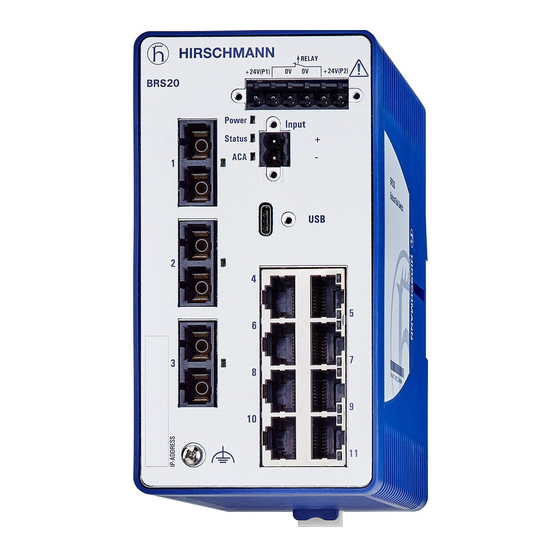
Device views 1.3.1 Front view Example of a device variant with 4 ... 6 ports without PoE BRS20 RELAY +24V(P1) +24V(P2) Power Input Status 6-pin terminal block with screw lock for redundant power supply and signal contact 2-pin terminal block with screw lock for the digital input depending on device variant ... - Page 31 Example of a device variant with 8 ... 12 ports with PoE Power Input Status LED display elements for device status 2-pin terminal block with screw lock for the digital input 6-pin terminal block with screw lock for redundant power supply and signal contact USB-C interface depending on the device variants BRS22/32...
- Page 32 Example of a device variant with 8 ... 24 ports without PoE RELAY 24V(P1) 24V(P2) Power Input Stat. 6-pin terminal block with screw lock for redundant power supply and signal contact LED display elements for device status LED display elements for port status depending on the device variants ...
-
Page 33: Rear View
depending on the device variants BRS20/30 8 × RJ45 socket for 10/100 Mbit/s twisted pair connections 16 × RJ45 socket for 10/100 Mbit/s twisted pair connections BRS40/50 8 × RJ45 socket for 10/100/1000 Mbit/s twisted pair connections ... -
Page 34: Power Supply
Power supply 1.4.1 Supply voltage with characteristic value T The following options for power supply are available: 6-pin terminal block You will find information on connecting the supply voltage here: See “Supply voltage with characteristic value T” on page 51. 1.4.2 Supply voltage with characteristic value F The following options for power supply are available:... -
Page 35: Ethernet Ports
Ethernet ports You can connect end devices and other segments to the device ports using twisted pair cables or optical fibers (F/O). 1.5.1 10/100 Mbit/s twisted pair port This port is an RJ45 socket. The 10/100 Mbit/s twisted pair port allows you to connect network components according to the IEEE 802.3 10BASE-T/100BASE-TX standard. - Page 36 The 100/1000/2500 Mbit/s twisted pair port allows you to connect network components according to the IEEE 802.3 100BASE-TX/1000BASE-T and IEEE 802.3bz 2.5GBASE-T standards. This port supports: Autonegotiation Autopolarity Autocrossing (if autonegotiation is activated) 100/1000/2500 Mbit/s full duplex Delivery state: Autonegotiation activated The port casing is electrically connected to the front panel.
-
Page 37: 100 Mbit/S F/O Port
1.5.4 100 Mbit/s F/O port This port is a DST/DSC socket or an SFP slot. The 100 Mbit/s F/O port allows you to connect network components according to the IEEE 802.3 100BASE-FX standard. This port supports: 100 Mbit/s, full duplex Delivery state: ... -
Page 38: Support Of Poe(+)
The port allows you to connect network components according to IEEE P802.3bz 2.5 Gbit/s. This port supports: 100 Mbit/s full duplex 1000 Mbit/s full duplex 2500 Mbit/s full duplex Delivery state: 100 Mbit/s full duplex when using a Fast Ethernet SFP transceiver ... -
Page 39: Display Elements
Display elements 1.6.1 Device state These LEDs provide information about conditions which affect the operation of the whole device. Power Power Power Status Status Status Figure 1: LED display elements for device status Display Color Activity Meaning Power Supply voltage —... -
Page 40: Port Status
1.6.2 Port status These LEDs display port-related information. Note: For device variants with 4 × RJ45 sockets: The LEDs are directly located at the ports. See figure 2 on page 40. For device variants with 8 × RJ45 sockets: The LEDs are located on the right side of the device. - Page 41 LS/DA LS/DA Figure 3: LED display elements for device variants with DSC, DST and 8 × RJ45 sockets LS/DA LS/DA Figure 4: LED display elements for device variants with SFP slots and 8 × RJ45 sockets Installation BRS20/22/30/32/40/42/50/52 Release 12 01/2022...
- Page 42 RELAY +24V(P1) +24V(P2) Power Input Stat. LS/DA LS/DA LS/DA Figure 5: LED display elements for a high port device variant with SFP slots and 20 × RJ45 sockets Display Color Activity Meaning LS/DA — none Device detects an invalid or missing link Link status green lights up...
-
Page 43: Management Interfaces
Management interfaces 1.7.1 Signal contact RELAY 0.5 Nm 4.4 lb-in Figure 6: (1) Connection on the device, (2) terminal block mounted on the device (front view), tightening torque, (3) terminal block mounted on the device (view from above). The signal contact is a potential-free relay contact. The signal contact is open when the device is not connected to a power supply. -
Page 44: Usb-C Interface
1.7.2 USB-C interface Name Pin Pin Name V BUS V BUS ACA22-USB-C (EEC) V BUS V BUS Figure 7: (1) Position of the USB-C interface on the device, (2) pin assignment of the USB-C interface, (3) view of the ACA22-USB-C (EEC). The USB-C interface allows you to connect the AutoConfiguration Adapter ACA22-USB-C (EEC) storage medium. -
Page 45: Digital Input
Voltage not electrically insulated Supported file system: FAT32 Note: A USB cable is used exclusively for the configuration of your device. Note: The ACA22-USB-C (EEC) storage medium can remain permanently connected to the device. 1.7.3 Digital input Input 0.5 Nm 4.4 lb-in Figure 8: (1) Connection on the device, (2) terminal block mounted on the device... -
Page 46: Hardware Revision
1.7.4 Hardware revision Hardware revision 2 BRS device variants marked as "HW: Rev. 2" only support SW versions as of 08.7.02. You find the revision marking of your device on the side label. Uin : x,x - xx V Iin : x,x - x,xx A BRSxx Uin : x,x - xx V... -
Page 47: Installation
Installation The devices have been developed for practical application in a harsh industrial environment. On delivery, the device is ready for operation. Perform the following steps to install and configure the device: Checking the package contents Installing and grounding the device ... - Page 48 Mounting Minimum clearance at Temperature derating the ventilation slots Standard mounting (vertical) 5 cm (2 in) 0 °K 2 cm (0.8 in) 3 °K 0 cm (0 in) 15 °K 90° rotated mounting (horizontal) 0 cm (0 in) 15 °K Table 6: Derating for different mounting positions Figure 11: Mounting on the DIN rail...
-
Page 49: Grounding The Device
2.2.2 Grounding the device 0.5 Nm 4.4 lb-in Figure 12: Position of the ground connection on the device; tightening torque. All device variants have a functional ground connection. Perform the following work steps: Ground the device via the ground screw. 2.2.3 Connecting the ferrite (optional) Exclusively applies to device variants with 8 ... -
Page 50: Installing An Sfp Transceiver (Optional)
Installing an SFP transceiver (optional) Prerequisites: Exclusively use Hirschmann SFP transceivers. See “Accessories” on page 103. Figure 13: Installing SFP transceivers: Installation sequence Perform the following work steps: Take the SFP transceiver out of the transport packaging (1). Remove the protection cap from the SFP transceiver (2). ... - Page 51 Supply voltage with characteristic value T RELAY +24 V(P1) +24 V(P2) 0V 0V 12 V DC ... 24 V DC 12 V DC ... 24 V DC 0.5 Nm 4.4 lb-in Figure 14: (1) DC voltage connection on the device, (2) terminal block mounted on the device (front view), tightening torque, (3) terminal block mounted on the device (view from above).
- Page 52 Supply voltage with characteristic value F RELAY +24 V(P1) +24 V(P2) 0V 0V 24 V DC ... 48 V DC 24 V DC ... 48 V DC RELAY +24 V(P1) +24 V(P2) 0 V 0 V 24 V AC 24 V AC 0.5 Nm 4.4 lb-in...
- Page 53 Fasten the wires in the terminal block by tightening the terminal screws. Mount the terminal block on the device using screws. Supply voltage with characteristic value U RELAY +24 V(P1) +24 V(P2) 0 V 0 V Power Input Status 0.5 Nm...
- Page 54 Supply voltage with characteristic value P RELAY +54 V(P1) +54 V(P2) 0 V 0 V Power Status 2.5 GE 2.5 GE 0.5 Nm 4.4 lb-in 2.5 GE 2.5 GE Figure 17: (1) DC voltage connection on the device, (2) terminal block mounted on the device (front view), tightening torque, (3) terminal block mounted on the device (view from above).
-
Page 55: Signal Contact (Optional)
Fasten the wires in the terminal block by tightening the terminal screws. Mount the terminal block on the device using screws. 2.4.2 Signal contact (optional) RELAY 0.5 Nm 4.4 lb-in Figure 18: (1) Connection on the device, (2) terminal block mounted on the device (front view), tightening torque, (3) terminal block mounted on the device (view from above). -
Page 56: Digital Input (Optional)
2.4.3 Digital input (optional) Input 0.5 Nm 4.4 lb-in Figure 19: (1) Connection on the device, (2) terminal block mounted on the device (front view), tightening torque. Signal, terminal Function DI (+) Signal input DI (−) Reference potential Table 11: Digital input: pin assignment Perform the following work steps: ... -
Page 57: Operating The Device
Connection constellations of sensors Input + 24 V + 24 V Figure 20: Connection of a sensor (3 pin) with separate power supply 1 - Sensor 2 - BRS20/22/30/32/40/42/50/52l 3 - Separate power supply for sensor Input +24 V Figure 21: Connection of a sensor (2 pin) with separate power supply 1 - Sensor (2 pin sensor) 2 - BRS20/22/30/32/40/42/50/52l... -
Page 58: Connecting Data Cables
Connecting data cables Note the following general recommendations for data cable connections in environments with high electrical interference levels: Keep the length of the data cables as short as possible. Use optical data cables for the data transmission between the buildings. ... -
Page 59: Making Basic Settings
Making basic settings Note: 2 or more devices configured with the same IP address can cause unpredictable operation of your network. Install and maintain a process that assigns a unique IP address to every device in the network. The IP parameters must be entered when the device is installed for the first time. - Page 60 Log on to the device again with your new password. Note: If you lost your password, then use the System Monitor to reset the password. For further information see: https://hirschmann-support.belden.com/en/kb/required-password-change- new-procedure-for-first-time-login Installation BRS20/22/30/32/40/42/50/52 Release 12 01/2022...
-
Page 61: Monitoring The Ambient Air Temperature
Monitoring the ambient air temperature Operate the device below the specified maximum ambient air temperature exclusively. See “Climatic conditions during operation” on page 82. The ambient air temperature is the temperature of the air at a distance of 5 cm (2 in) from the device. It depends on the installation conditions of the device, for example the distance from other devices or other objects, and the output of neighboring devices. -
Page 62: Maintenance And Service
Maintenance and service When designing this device, Hirschmann largely avoided using high-wear parts. The parts subject to wear and tear are dimensioned to last longer than the lifetime of the product when it is operated normally. Operate this device according to the specifications. ... -
Page 63: Disassembly
Disassembly Removing an SFP transceiver (optional) Figure 22: De-installing SFP transceivers: De-installation sequence Perform the following work steps: Open the locking mechanism of the SFP transceiver (1). Pull the SFP transceiver out of the slot via the open locking mechanism (2). -
Page 64: Removing The Device
Removing the device Figure 23: Removal from the DIN rail Perform the following work steps: Disconnect the data cables. Disable the supply voltage. Disconnect the terminal blocks. Disconnect the grounding. Insert a screwdriver horizontally below the casing into the locking gate. ... -
Page 65: Technical Data
Technical data General data Product name Weight Weight Casing width Degree of Degree of Digital input (Plastic casing) (Metal casing) See “Dimension protection protection available drawings” on (Plastic casing) (Metal casing) page 84. BRS20 device variants BRS20-0400... 380 g (12.22 oz) 30.69 oz (870 g) narrow IP30 IP40... - Page 66 Product name Weight Weight Casing width Degree of Degree of Digital input (Plastic casing) (Metal casing) See “Dimension protection protection available drawings” on (Plastic casing) (Metal casing) page 84. BRS20-20009999-S;C... 1060 g (37.3 oz) 1700 g (60 oz) wide IP30 IP40 BRS20-20009999-T;E;G...
- Page 67 Product name Weight Weight Casing width Degree of Degree of Digital input (Plastic casing) (Metal casing) See “Dimension protection protection available drawings” on (Plastic casing) (Metal casing) page 84. BRS30-16042T2T-S;C... 1060 g (37.3 oz) 1700 g (60 oz) wide IP30 IP40 BRS30-16042T2T-T;E;G...
- Page 68 Product name Weight Weight Casing width Degree of Degree of Digital input (Plastic casing) (Metal casing) See “Dimension protection protection available drawings” on (Plastic casing) (Metal casing) page 84. BRS32-0804OOOO-T;E;G... not available 1300 g (45.85 oz) wide not available IP30 BRS33 PoE device variants featuring supply voltage with characteristic value U BRS33-0804OOOO-S;C 930 g (32.80 oz) 1610 g (56.79 oz)
- Page 69 Product name Weight Weight Casing width Degree of Degree of Digital input (Plastic casing) (Metal casing) See “Dimension protection protection available drawings” on (Plastic casing) (Metal casing) page 84. BRS41-0020OOOO-T;E;G... not available 1680 g (59.26 oz) wide not available IP30 BRS41-0024OOOO-S;C...
- Page 70 Product name Weight Weight Casing width Degree of Degree of Digital input (Plastic casing) (Metal casing) See “Dimension protection protection available drawings” on (Plastic casing) (Metal casing) page 84. BRS50-00122Q2Q… 570 g (20.10 oz) 1090 g (38.45 oz) medium IP30 IP40 BRS50-0020QTQT-S;C…...
- Page 71 General data Dimensions See “Dimension drawings” on page 84. W × H × D Mounting See “Installing the device onto the DIN rail” on page 47. Pollution degree Degree of IP30 protection See “General data” on page 65. IP40 See “General data” on page 65. Note: IP protection is not evaluated by UL.
-
Page 72: Temperature Ranges
Temperature ranges Gilt für alle Gerätevarianten: Note the following deratings: Mounting: See “Installing and grounding the device” on page 47. transceiver:See “Derating due to SFP transceiver” on page 98. PoE power: See “Supply voltage with characteristic value U” on page 77. “Supply voltage with characteristic value P”... - Page 73 Product name Temperature range Temperature range Characteristic value S, C Characteristic value T, E, G BRS22 PoE device variants featuring supply voltage with characteristic value P BRS22-0800... 0 °C ... +60 °C (+32 °F ... -40 °C ... +70 °C (-40 °F ... +140 °F) +158 °F) Metal casing: maximum...
- Page 74 Product name Temperature range Temperature range Characteristic value S, C Characteristic value T, E, G BRS33-0804... 0 °C ... +50 °C (+32 °F ... -40 °C ... +60 °C (-40 °F ... +122 °F) +140 °F) BRS40 device variants BRS40-0008... 0 °C ...
- Page 75 Product name Temperature range Temperature range Characteristic value S, C Characteristic value T, E, G BRS42-0012... 0 °C ... +60 °C (+32 °F ... -40 °C ... +70 °C (-40 °F ... +140 °F) +158 °F) Metal casing: maximum 240 W PoE power Plastic casing: maximum 120 W PoE power...
-
Page 76: Supply Voltage
Product name Temperature range Temperature range Characteristic value S, C Characteristic value T, E, G BRS52-0012QTQT... 0 °C ... +50 °C (+32 °F ... -40 °C ... +60 °C (-40 °F ... +122 °F) +140 °F) BRS52-00122Q2Q... 0 °C ... +60 °C (+32 °F ... -40 °C ... - Page 77 Supply voltage with characteristic value F Connection type 6-pin terminal block with screw lock Tightening torque 0.5 Nm (4.4 lb-in) min. conductor diameter 0.75 mm² (AWG18) max. conductor diameter 2.5 mm² (AWG12) Power loss buffer >10 ms at 20.4 V DC ... 48 V DC and 24 V AC Overload current protection on the Non-replaceable fuse device...
- Page 78 Supply voltage with characteristic value P Max. PoE power 240 W 0 °C ... +50 °C (+32 °F ... +122 °F) ambient air temperature Ambient air temperature 180 W > +50 °C ... +55 °C (+122 °F ... +131 °F) ambient air temperature 120 W >...
-
Page 79: Power Consumption/Power Output
Power consumption/power output Device name Total power Thermal power PoE power output consumption output BRS20-0400... 17 Btu (IT)/h BRS20-0500... 20 Btu (IT)/h BRS20-0600... 24 Btu (IT)/h BRS20-0800... 20 Btu (IT)/h BRS20-0900... 24 Btu (IT)/h BRS20-1000... 27 Btu (IT)/h BRS20-1100... 31 Btu (IT)/h BRS20-1200... -
Page 80: Signal Contact
Signal contact Signal contact Device variants featuring supply voltage with characteristic value F, P and T Connection type 6-pin terminal block with screw lock Tightening torque 0.5 Nm (4.4 lb-in) min. conductor diameter 0.08 mm (AWG 28) max. conductor diameter 2.5 mm²... -
Page 81: Digital Input
Digital input Digital input Connection type 2-pin terminal block with screw lock Tightening torque 0.5 Nm (4.4 lb-in) min. conductor 0.08 mm (AWG 28) diameter max. conductor 2.5 mm² (AWG12) diameter Maximum permitted input voltage range between -32 V DC and +32 V DC Nominal input voltage +24 V DC Input voltage, low level, status “0”... -
Page 82: Climatic Conditions During Operation
Climatic conditions during operation Climatic conditions during operation Minimum See “Installing the device onto the DIN rail” on page 47. clearance at the ventilation slots Ambient air Standard temperature up to 2000 m ASL (6562 ft ASL) 0 °C ... +60 °C (+32 °F ... +140 °F) ... -
Page 83: Climatic Conditions During Storage
Climatic conditions during operation Air pressure Without derating min. 795 hPa (+2000 m ASL; +6562 ft ASL) max. 1060 hPa (-400 m ASL; -1312 ft ASL) With derating min. 540 hPa (+4000 m ASL; +13123 ft ASL) ... -
Page 84: Dimension Drawings
Dimension drawings 7.9.1 Device variants with casing with characteristic value C (plastic casing) inch 12,3 0.48 103,5 2.24 4.07 14,9 0.59 Figure 24: Device variants in narrow plastic casing Installation BRS20/22/30/32/40/42/50/52 Release 12 01/2022... - Page 85 inch 11,8 103,5 0.46 2.87 4.07 14,9 0.59 Figure 25: Device variants in medium plastic casing Installation BRS20/22/30/32/40/42/50/52 Release 12 01/2022...
- Page 86 inch 108,8 103,5 11,8 4.28 0.46 4.07 14,9 0.59 Figure 26: Device variants in wide plastic casing Installation BRS20/22/30/32/40/42/50/52 Release 12 01/2022...
-
Page 87: Device Variants With Casing With Characteristic Value E/D (Metal Casing)
7.9.2 Device variants with casing with characteristic value E/D (metal casing) inch 10,3 0.41 4,55 70,7 105,5 2.78 0.18 4.15 0.59 Figure 27: Device variants in narrow metal casing Installation BRS20/22/30/32/40/42/50/52 Release 12 01/2022... - Page 88 inch 86,6 0.39 105,5 4,55 3.41 0.18 4.15 0.59 Figure 28: Device variants in medium metal casing Installation BRS20/22/30/32/40/42/50/52 Release 12 01/2022...
- Page 89 inch 122,4 4,55 105,5 4.82 0.18 4.15 0.39 0.59 Figure 29: Device variants in wide metal casing Installation BRS20/22/30/32/40/42/50/52 Release 12 01/2022...
-
Page 90: Immunity
7.10 Immunity Immunity Standard applications Navy applications Railway applications (trackside) as per EN 50121-4 IEC 60068-2-6, test Fc Vibration 5 Hz ... 8.4 Hz with 3.5 mm 2 Hz ... 13.2 Hz with 1 mm — (0.14 in) amplitude (0.04 in) amplitude 8.4 Hz ... - Page 91 EMC interference immunity Standard Navy Railway applications applications applications (trackside) as per EN 50121-4 Electrostatic discharge EN 61000-4-2 Contact discharge ±4 kV ±6 kV ±6 kV EN 61000-4-2 Air discharge ±8 kV ±8 kV ±8 kV Electromagnetic field EN 61000-4-3 80 MHz ...
-
Page 92: Network Range
7.12 Network range Note: The line lengths specified for the transceivers apply for the respective fiber data (fiber attenuation and Bandwidth Length Product (BLP)/ Dispersion). 7.12.1 10/100/1000 Mbit/s twisted pair port 10/100/1000 Mbit/s twisted pair port Length of a twisted pair segment max. - Page 93 Product code Mode Wave length Fiber System Example for F/O Fiber BLP/Dispersion attenuation cable length attenuation M-FAST-SFP-LH/LC... 1550 nm 9/125 µm 10 dB ... 29 dB 55 km ... 140 km 0.18 dB/km 18 ps/(nm×km) (14.29 mi ... 86.99 mi) SFP-FAST-MM/LC 1310 nm 50/125 µm...
-
Page 94: Gigabit Ethernet Sfp Transceiver
Product code Mode Wave length Fiber System Example for F/O Fiber attenuation BLP/Dispersion attenuation cable length -E2, EE 1300 nm 9/125 µm 7 dB ... 29 dB 25 km ... 65 km 0.4 dB/km 3.5 ps/(nm×km) (12.43 mi ... 40.39 mi) -L2, -LL 1550 nm 9/125 µm... - Page 95 Product code Mode Wave length Fiber System Example for F/O Fiber M-SFP-... attenuation cable length attenuation Dispersion -LX/LC... 1310 nm 62.5/125 µm 0 dB ... 10.5 dB 0 km ... 0.55 km 1.0 dB/km 500 MHz×km (0 mi ... 0.34 mi) -LX/LC...
-
Page 96: Gigabit Ethernet Sfp Transceiver
c. Using the bandwidth-length product is inappropriate for expansion calculations. d. With F/O adapter compliant with IEEE 802.3-2002 Clause 38 (single-mode fiber offset-launch mode conditioning patch cord). e. With F/O adapter compliant with IEEE 802.3-2002 Clause 38 (single-mode fiber offset-launch mode conditioning patch cord). Including 2.5 dB system reserve when compliance with the fiber data is observed. -
Page 97: Bidirectional Fast Ethernet Sfp Transceiver
7.12.5 Bidirectional Fast Ethernet SFP transceiver Product code Mode Wave length Wave length Fiber System Example for F/O Fiber Dispersion SFP-FAST-B... attenuation cable length attenuation SFP-FAST-BA 1310 nm 1550 nm 50/125 µm 0 dB ... 16 dB 0 km ... 2 km 1.0 dB/km 800 MHz×km MM/LC EEC... -
Page 98: Derating Due To Sfp Transceiver
Product code Mode Wave length Wave length Fiber System Example for F/O Fiber Dispersion SFP-GIG-B... attenuation cable length attenuation SFP-GIG-BB LX+/ 1550 nm 1310 nm 9/125 µm 3 dB ... 20 dB 12 km ... 40 km 0.25 dB/km 19 ps/(nm×km) LC EEC (7.45 mi ... -
Page 99: Gigabit Ethernet Sfp Transceiver
Product code Derating for a device with operating Derating for a device with operating Order number temperature +60 °C (+140 °F) per SFP temperature +70 °C (+158 °F) per SFP transceiver used transceiver used M-FAST SFP-SM+/LC 943 867-001 M-FAST SFP-SM+/LC EEC 0 K 943 947-001 M-FAST SFP-LH/LC 943 868-001... -
Page 100: Gigabit Ethernet Sfp Transceiver
Product code De-rating for a device with De-rating for a device with Order number operating temperature +60 °C operating temperature +70 °C (+140 °F) per SFP transceiver (+158 °F) per SFP transceiver used used M-SFP-LH+/LC 943 049-001 M-SFP-TX/RJ45 943 977-001 M-SFP-TX/RJ45 EEC 942 161-001 SFP-GIG-LX/LC... -
Page 101: Bidirectional Fast Ethernet Sfp Transceiver
7.13.4 Bidirectional Fast Ethernet SFP transceiver Product code De-rating for a device with operating De-rating for a device with operating Order number temperature +60 °C (+140 °F) per SFP temperature +70 °C (+158 °F) per SFP transceiver used transceiver used SFP-FAST-BA MM/LC EEC 942 204-001 SFP-FAST-BB MM/LC EEC... -
Page 102: Scope Of Delivery
Scope of delivery Scope of delivery 1 × Device 1 × Safety and general information sheet 1 × Terminal block for supply voltage and signal contact 1 × Terminal block for the digital input depending on device variant 2 × Ferrites with key depending on device variant See “Connecting the ferrite (optional)”... -
Page 103: Accessories
Accessories General accessories General accessories You find more information on available accessories in the Belden Online Catalog https:/ /catalog.belden.com AutoConfiguration Adapter ACA22-USB-C (EEC) 942-239-001 6-pin terminal block with screw lock (10 pieces) 972 272-303 6-pin terminal block with screw lock (50 pieces) - Page 104 Name Order number BRS20-8TX/2FX-SM-HL 942 170-028 BRS20-4TX/2SFP-HL 942 170-029 BRS20-4TX-EEC-HL 942 170-034 BRS20-8TX-EEC-HL 942 170-035 BRS20-4TX/2FX-EEC-HL 942 170-036 BRS20-8TX/2FX-EEC-HL 942 170-037 BRS20-4TX/2FX-SM-EEC-HL 942 170-038 BRS20-8TX/2FX-SM-EEC-HL 942 170-039 BRS20-4TX/2SFP-EEC-HL 942 170-040 BRS20-16TX 942 170-053 BRS20-16TX-EEC 942 170-054 BRS20-16TX/4SFP 942 170-055 BRS20-16TX/4SFP-EEC 942 170-056 BRS20-20TX/4SFP 942 170-057...
-
Page 105: Fast Ethernet Sfp Transceiver
Name Order number BRS32-8TX/4SFP 942 170-048 BRS32-8TX/4SFP-EEC 942 170-052 BRS42-8TX 942 170-047 BRS42-8TX-EEC 942 170-051 BRS42-8TX/4SFP 942 170-046 BRS42-8TX/4SFP-EEC 942 170-050 BRS52-8TX/4SFP 942 170-045 BRS52-8TX/4SFP-EEC 942 170-049 Table 42: Order numbers for standard variants in plastic casing Fast Ethernet SFP transceiver Fast Ethernet SFP transceiver Certification type Temperature Order number... -
Page 106: Gigabit Ethernet Sfp Transceiver
Fast Ethernet SFP transceiver Certification type Temperature Order number range SFP-FAST-SM/LC Entry level 0 °C ... +60 °C 942 195-001 (+32 °F ... +140 °F) SFP-FAST-SM/LC EEC Entry level 0 °C ... +70 °C 942 195-002 (+32 °F ... +158 °F) Table 43: Accessory: Fast Ethernet SFP transceiver a. -
Page 107: Gigabit Ethernet Sfp Transceiver
2.5 Gigabit Ethernet SFP transceiver 2.5 Gigabit Ethernet Certification Temperature range Order number SFP transceiver type M-SFP-2.5-MM/LC EEC Standard level 0 °C ... +70 °C (+32 °F ... 942 162-001 +158 °F) M-SFP-2.5-SM-/LC EEC Standard level 0 °C ... +70 °C (+32 °F ... 942 163-001 +158 °F) M-SFP-2.5-SM/LC EEC... -
Page 108: Bidirectional Gigabit Ethernet Sfp Transceiver
Bidirectional Gigabit Ethernet SFP transceiver Bidirectional Gigabit Certification Temperature range Order Ethernet SFP transceiver type number SFP-GIG-BA LX/LC EEC Entry level 0 °C ... +70 °C (+32 °F ... 942 207-001 +158 °F) SFP-GIG-BB LX/LC EEC Entry level 0 °C ... +70 °C (+32 °F ... 942 207-002 +158 °F) SFP-GIG-BA LX+/LC EEC Entry level... -
Page 109: 10 Underlying Technical Standards
10 Underlying technical standards Name ANSI/UL 121201 Nonincendive Electrical Equipment for Use in Class I and II, Division 2 and Class III, Divisions 1 and 2 Hazardous (Classified) Locations DNV-CG-0339 Environmental test specification for electrical, electronic and programmable equipment and systems. FCC 47 CFR Part 15 Code of Federal Regulations NEMA TS 2... -
Page 110: A Further Support
You find the addresses of our partners on the Internet at http://www.hirschmann.com. A list of local telephone numbers and email addresses for technical support directly from Hirschmann is available at https://hirschmann-support.belden.com. This site also includes a free of charge knowledge base and a software download section. Customer Innovation Center... - Page 111 Installation BRS20/22/30/32/40/42/50/52 Release 12 01/2022...
Need help?
Do you have a question about the HIRSCHMANN BRS20 and is the answer not in the manual?
Questions and answers
Dear, we need information about the switch BRS30 that maximum how many switches we can configure in the series one loop.