
Related Manuals for Belden HIRSCHMANN RSP20


Summary of Contents for Belden HIRSCHMANN RSP20
- Page 1 User Manual Installation Industrial Ethernet Rail Switch Power RSP20/25/30/35 Installation RSP20/25/30/35 Technical support Release 18 09/2021 https://hirschmann-support.belden.com...
- Page 2 The naming of copyrighted trademarks in this manual, even when not specially indicated, should not be taken to mean that these names may be considered as free in the sense of the trademark and tradename protection law and hence that they may be freely used by anyone. ©...
-
Page 3: Table Of Contents
Contents Important information Safety instructions About this manual Description General description Device name and product code Device views 1.3.1 Front view 1.3.2 Rear view Power supply 1.4.1 Supply voltage with the characteristic value K9 1.4.2 Supply voltage with the characteristic value KK 1.4.3 Supply voltage with the characteristic value TT 1.4.4 Supply voltage with the characteristic value CC Ethernet ports... - Page 4 Installing and grounding the device 2.3.1 Installing the device onto the DIN rail 2.3.2 Grounding the device Installing an SFP transceiver (optional) Connecting the terminal blocks 2.5.1 Supply voltage with the characteristic value K9 2.5.2 Supply voltage with the characteristic value KK 2.5.3 Supply voltage with the characteristic value CC 2.5.4 Supply voltage with the characteristic value TT 2.5.5 Signal contact...
-
Page 5: Important Information
Important information Note: Read these instructions carefully, and familiarize yourself with the device before trying to install, operate, or maintain it. The following notes may appear throughout this documentation or on the device. These notes warn of potential hazards or call attention to information that clarifies or simplifies a procedure. - Page 6 NOTICE NOTE provides information about procedures that do not involve the risk of injury. Installation RSP20/25/30/35 Release 18 09/2021...
-
Page 7: Safety Instructions
Safety instructions WARNING UNCONTROLLED MACHINE ACTIONS To avoid uncontrolled machine actions caused by data loss, configure all the data transmission devices individually. Before you start any machine which is controlled via data transmission, be sure to complete the configuration of all data transmission devices. Failure to follow these instructions can result in death, serious injury, or equipment damage. - Page 8 Installation site requirements If you connect the device to a power supply that does NOT meet the requirements for Limited Power Source, NEC Class 2 or PS2 according to IEC/EN 62368-1 and is NOT limited to 100 W output power, the device must be installed in either a switch cabinet or other fire enclosure.
- Page 9 Qualified personnel have the following characteristics: Qualified personnel are properly trained. Training as well as practical knowledge and experience make up their qualifications. This is the prerequisite for grounding and labeling circuits, devices, and systems in accordance with current standards in safety technology. ...
- Page 10 Requirements for connecting the supply voltage Device variant Requirements All variants All of the following requirements are complied with: The supply voltage corresponds to the voltage specified on the type plate of the device. The power supply conforms to overvoltage category I or II. ...
- Page 11 Device variant Requirements Only device variants If you connect 2 independent power sources, verify that the minus featuring supply terminal is grounded. Failure to follow this instruction can result in voltage with equipment damage. characteristic value The wire diameter of the power supply cable is at least 0.75 mm² (North America: AWG18) on the supply voltage input.
- Page 12 ATEX directive 2014/34/EU – specific regulations for safe operation Relevant for RSP devices when operating in explosive gas atmospheres according to ATEX directive 2014/34/EU, the following applies: List of standards: EN IEC 60079-0:2018 EN 60079-7:2015 + A1:2018 EN IEC 60079-15:2019 ...
- Page 13 UK conformity regulations 2016, UK S.I. 2016:1107 (as amended by UK S.I. 2019:696) - Schedule 3A, Part 6 Relevant for RSP devices when operating in explosive gas atmospheres the following applies: List of standards: EN IEC 60079-0:2018 EN 60079-7:2015 + A1:2018 EN IEC 60079-15:2019 ...
- Page 14 Relevant for use in explosion hazard areas (Hazardous Locations, Class I, Division 2): The relay connections are to be installed and used within their Entity Parameters as per Control Drawing 000189237DNR. Avertissement - Risque d'explosion - Ne pas débrancher tant que le circuit est sous tension à...
- Page 15 For Use in Hazardous Locations Class I Division 2 Groups A, B, C, D: Only allowed for RSP 20/25/30/35 model No´s. which are individually labeled “FOR USE IN HAZARDOUS LOCATIONS”. Nonincendive fi eld wiring circuits must be wired in accordance with the National Electrical Code (NEC), NFPA 70, article 501;...
- Page 16 Ordinary Location, Explosive Atmosphere Class I Division 2 Non-Hazardous Area, Groups A, B, C, D Non-Explosive Atmosphere Hazardous Location Relay contacts: Equipment with nonincendive ¿ eld wiring parameters. Polarity is not relevant. The relay terminals are dependent upon the following Entity parameters: 30 V 90 mA...
- Page 17 IECEx – Certification Scheme for Explosive Atmospheres For RSP devices labeled with an IECEx certificate number, the following applies: List of standards: IEC 60079-0:2017 IEC 60079-7:2017 IEC 60079-15:2017 Use only device variants featuring supply voltage with characteristic value CC.
- Page 18 CE marking The labeled devices comply with the regulations contained in the following European directive(s): Device variant Directive All variants 2014/30/EU (EMC) Directive of the European Parliament and of the Council on the harmonisation of the laws of the Member States relating to electromagnetic compatibility.
- Page 19 UK S.I. 2019:696) - Schedule 3A, Part 6” on page 13. The UKCA conformity declaration will be available to the relevant authorities at the following address: Belden UK Ltd. 1 The Technology Centre, Station Road Framlingham, IP13 9EZ, United Kingdom...
- Page 20 Supplier's Declaration of Conformity 47 CFR § 2.1077 Compliance Information RSP20/25/30/35 U.S. Contact Information Belden – St. Louis 1 N. Brentwood Blvd. 15th Floor St. Louis, Missouri 63105, United States Phone: 314.854.8000 This device complies with part 15 of the FCC Rules. Operation is subject...
-
Page 21: About This Manual
About this manual The “Installation” user manual contains a device description, safety instructions, a description of the display, and the other information that you need to install the device. Documentation mentioned in the “User Manual Installation” that is not supplied with your device as a printout can be found as PDF files for downloading on the Internet at: https://www.doc.hirschmann.com Installation RSP20/25/30/35... -
Page 22: Key
The symbols used in this manual have the following meanings: Listing Work step Subheading Installation RSP20/25/30/35 Release 18 09/2021... -
Page 23: Description
Description General description The RSP20/25/30/35 devices are designed for the special requirements of industrial automation. They meet the relevant industry standards, provide very high operational reliability, even under extreme conditions, and also long-term reliability and flexibility. You can choose from between a wide range of variants. You have the option to set up your device individually based on different criteria: ... -
Page 24: Device Name And Product Code
The characteristic values stand for specific product properties. You have numerous options of combining the device characteristics. You can determine the possible combinations using the configurator which is available in the Belden Online Catalog https://catalog.belden.com on the web page of the device. - Page 25 Item Characteristic Character Description istic value Temperature range Standard +32 °F ... +140 °F (0 °C ... +60 °C) Extended -40 °F ... +158 °F (-40 °C ... +70 °C) Extended with -40 °F ... +158 °F (-40 °C ... Conformal Coating +70 °C) 18 ...
- Page 26 Application case Certificates and declarations Characteristic value Standard applications ATEX/IECEx, Zone 2 ANSI/UL 121201 EN 61131-2 UL 508 Substation applications IEC 61850-3 IEEE 1613 Navy applications DNV GL Railway applications EN 50121-4 (trackside) Table 5: Assignment: application cases, certificates and declarations, characteristic values...
-
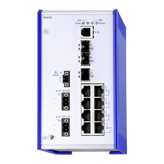
Page 27: Device Views
Device views 1.3.1 Front view Front view (using the example RSP20-11003Z6TT-SCC...) LED display elements for device status V.24 interface 3 × depending on device variant RSP20/RSP25 SFP slot for 100 Mbit/s connections RSP30/RSP35 SFP slot for 100/1000 Mbit/s connections 8× 10/100 Mbit/s twisted pair port 4 ×... -
Page 28: Rear View
Supply voltage connection alternatively, Supply voltage with the 2 voltage inputs for redundant power supply depending on characteristic value: 2-pin terminal block device variant Supply voltage with the 1 voltage input 3-pin terminal block characteristic value: ... -
Page 29: Power Supply
Power supply You will find information on the characteristic values here: “Device name and product code” on page 24 1.4.1 Supply voltage with the characteristic value K9 The following options for power supply are available: 1 × 3-pin terminal block You will find information on connecting the supply voltage here: See “Supply voltage with the characteristic value K9”... -
Page 30: Ethernet Ports
Ethernet ports You can connect end devices and other segments to the device ports using twisted pair cables or optical fibers (F/O). 1.5.1 10/100 Mbit/s twisted pair port This port is an RJ45 socket. The 10/100 Mbit/s twisted pair port allows you to connect network components according to the IEEE 802.3 10BASE-T/100BASE-TX standard. -
Page 31: 100 Mbit/S F/O Port
1.5.3 100 Mbit/s F/O port This port is an SFP slot. The 100 Mbit/s F/O port allows you to connect network components according to the IEEE 802.3 100BASE-FX standard. This port supports: 100 Mbit/s half-duplex mode, 100 Mbit/s full duplex mode Default setting: Full duplex 1.5.4 100/1000 Mbit/s F/O port (optional) -
Page 32: Display Elements
Display elements After the supply voltage is set up, the Software starts and initializes the device. Afterwards, the device performs a self-test. During this process, various LEDs light up. 1.6.1 Device state These LEDs provide information about conditions which affect the operation of the whole device. -
Page 33: Port Status
Applies to software releases after 02.0.00: Display Color Activity Meaning Status Device Status — none Device is starting and/or is not ready for operation. green lights up Device is ready for operation. Characteristics can be configured lights up Device is ready for operation. Device has detected at least one error in the monitoring results flashes 1 time... -
Page 34: Management Interfaces
Management interfaces 1.7.1 V.24 interface (external management) A serial interface is provided on the RJ11 socket (V.24 interface) for the local connection of an external management station (VT100 terminal or PC with corresponding terminal emulation). This enables you to set up a connection to the Command Line Interface CLI and to the System Monitor. -
Page 35: Signal Contact
Signal contact Figure 2: Signal contact: 2-pin terminal block with screw locking The signal contact is a potential-free relay contact. The signal contact is open when the device is not connected to a power supply. The signal contact allows you to control external devices or monitor device functions. -
Page 36: Installation
Installation The devices have been developed for practical application in a harsh industrial environment. On delivery, the device is ready for operation. Perform the following steps to install and configure the device: Checking the package contents Installing the SD card (optional) ... -
Page 37: Installing And Grounding The Device
Installing and grounding the device WARNING FIRE HAZARD If you connect the device to a power supply that does NOT meet the requirements for Limited Power Source, NEC Class 2 or PS2 according to IEC/EN 62368-1 and is NOT limited to 100 W output power, the device must be installed in either a switch cabinet or other fire enclosure. -
Page 38: Grounding The Device
Note: The overall shield of a connected shielded twisted pair cable is connected to the grounding connector on the front panel as a conductor. 2.3.2 Grounding the device The device is grounded via the separate ground screw on the bottom left of the front side of the device. -
Page 39: Installing An Sfp Transceiver (Optional)
Installing an SFP transceiver (optional) Prerequisites: Exclusively use Hirschmann SFP transceivers. See “Accessories” on page 66. Figure 3: Installing SFP transceivers: Installation sequence Proceed as follows: Take the SFP transceiver out of the transport packaging (1). Remove the protection cap from the SFP transceiver (2). ... -
Page 40: Supply Voltage With The Characteristic Value K9
2.5.1 Supply voltage with the characteristic value K9 You will find information on the characteristic values here: “Device name and product code” on page 24 Figure 4: Supply voltage with the characteristic value K9: 3-pin terminal block with screw locking Type of the voltages Specification of the supply Pin assignment... -
Page 41: Supply Voltage With The Characteristic Value Kk
2.5.2 Supply voltage with the characteristic value KK You will find information on the characteristic values here: “Device name and product code” on page 24 You have the option of supplying the supply voltage redundantly, without load distribution. Both supply voltage inputs are uncoupled. With a redundant supply, the supply voltage 1 (upper voltage input on the device) has priority. -
Page 42: Supply Voltage With The Characteristic Value Cc
For every supply voltage to be connected, perform the following steps: Remove the terminal connector from the device. Connect the protective conductor with the clamp. Connect the wires according to the pin assignment on the device with the clamps. -
Page 43: Supply Voltage With The Characteristic Value Tt
For every supply voltage to be connected, perform the following steps: Remove the terminal connector from the device. Connect the wires according to the pin assignment on the device with the clamps. Fasten the wires in the terminal block by tightening the terminal screws. ... -
Page 44: Signal Contact
For every supply voltage to be connected, perform the following steps: Remove the terminal connector from the device. Connect the wires according to the pin assignment on the device with the clamps. Fasten the wires in the terminal block by tightening the terminal screws. ... -
Page 45: Operating The Device
Operating the device WARNING ELECTRIC SHOCK Before connecting the electrical wires, always verify that the requirements listed are complied with. See “Requirements for connecting electrical wires” on page 9. Ground the device before connecting any other cables. Failure to follow this instruction can result in death, serious injury, or equipment damage. -
Page 46: Filling Out The Inscription Label
Filling out the inscription label The information field for the IP address helps you identify your device. Installation RSP20/25/30/35 Release 18 09/2021... -
Page 47: Making Basic Settings
Making basic settings The IP parameters must be entered when the device is installed for the first time. The device provides the following options for configuring IP addresses: Input via the V.24 interface Input via the HiView or Industrial HiVision application. You find further information about the applications HiView or Industrial HiVision on the Internet at the Hirschmann product pages: HiView... - Page 48 Note: If you lost your password, then use the System Monitor to reset the password. For further information see: https://hirschmann-support.belden.com/en/kb/required-password- change-new-procedure-for-first-time-login Installation RSP20/25/30/35 Release 18 09/2021...
-
Page 49: Upgrading Software
Upgrading Software The upgrade options for RSP20/25/30/35 device depend on the software level of the device. See “Device name and product code” on page 24. Note: For software version 04.0 or higher, “HiOS” is available as a common software image for the software levels 2A and 3S. You select only the desired redundancy function during the installation of the image. -
Page 50: Monitoring The Ambient Air Temperature
Monitoring the ambient air temperature Operate the device below the specified maximum ambient air temperature exclusively. See “General technical data” on page 54. The ambient air temperature is the temperature of the air at a distance of 2 in (5 cm) from the device. It depends on the installation conditions of the device, for example the distance from other devices or other objects, and the output of neighboring devices. -
Page 51: Maintenance And Service
Maintenance and service When designing this device, Hirschmann largely avoided using high-wear parts. The parts subject to wear and tear are dimensioned to last longer than the lifetime of the product when it is operated normally. Operate this device according to the specifications. ... -
Page 52: Disassembly
Disassembly Removing the device WARNING ELECTRIC SHOCK Disconnect the grounding only after disconnecting all other cables. Failure to follow this instruction can result in death, serious injury, or equipment damage. Proceed as follows: Disconnect the data cables. Disable the supply voltage. ... -
Page 53: Removing An Sfp Transceiver (Optional)
Removing an SFP transceiver (optional) Figure 9: De-installing SFP transceivers: De-installation sequence Proceed as follows: Open the locking mechanism of the SFP transceiver (1). Pull the SFP transceiver out of the slot via the open locking mechanism (2). ... -
Page 54: Technical Data
Technical data General technical data Dimensions RSP20/25/30/35 See “Dimension drawings” on page 58. W × H × D Weight RSP 20/25/30/35-..TT- approx. 2.65 lb (1.2 kg) S..RSP 20/25/30/35-..TT- approx. 3.31 lb (1.5 kg) T..RSP 20/25/30/35-..TT- E..RSP 20/25/30/35-..ZT- approx. - Page 55 Supply voltage Rated voltage AC: 110 V AC ... 230 V AC, 50 Hz ... 60 Hz with the Voltage range AC incl. 88 V AC ... 265 V AC, 47 Hz ... 63 Hz characteristic maximum tolerances: value K9 and KK Rated voltage DC: 60 V DC ...
- Page 56 Climatic Ambient air temperature -40 °F ... +185 °F (-40 °C ... +85 °C) conditions during Humidity 5 % ... 95 % storage (non-condensing) Air pressure min. 700 hPa (+9842 ft; +3000 m) max. 1060 hPa (-1312 ft; -400 m) Signal contact (only for device variants featuring supply voltage with characteristic value CC and TT) Connection type...
- Page 57 When using supply voltage with characteristic value CC, K9 or KK: - applies when device is equipped with max. 4 SFP transceivers - if a higher number is connected, the following maximum values apply for the ambient air temperature: 5 to 7 transceivers: +176 °F (+80 °C) When using supply voltage with characteristic value TT: - applies when device is equipped with max.
-
Page 58: Dimension Drawings
Dimension drawings 114,7 6,55 4.52 inch 0.26 2.76 89,9 3.54 Figure 10: Dimensions of the device variants with operating temperature characteristic value S. For the characteristic value, cf. “Device name and product code” on page 114,7 6,55 4.52 inch 0.26 2.76 98,29 3.87... -
Page 59: Emc And Immunity
EMC and immunity You will find detailed information on the certificates and declarations applying to your device in a separate overview. See table 5 on page 26. Stability Standard Substation applications applications IEC 60068-2-6, test Fc Vibration — 2 Hz ... 9 Hz with 0.11 in (3 mm) amplitude 5 Hz ... - Page 60 EMC interference Standard Substation immunity applications applications Electromagnetic field EN 61000-4-3 80 MHz ... 3000 MHz max. 10 V/m max. 10 V/m IEEE 1613 80 MHz ... 1000 MHz — max. 35 V/m Fast transients (burst) EN 61000-4-4 AC/DC supply connection ±2 kV ±4 kV IEEE C37.90.1...
-
Page 61: Network Range
Network range Note: The line lengths specified for the transceivers apply for the respective fiber data (fiber attenuation and Bandwidth Length Product (BLP)/ Dispersion). Product code Wave length Fiber System Example for F/O Fiber attenuation BLP /Dispersion M-SFP-... attenuation cable length -SX/LC... - Page 62 Product code Wave length Fiber System Example for F/O Fiber attenuation BLP /Dispersion M-SFP-... attenuation cable length -LH+/LC 1550 nm 9/125 µm 15 dB ... 30 dB 44.12 mi ... 0.25 dB/km 19 ps/(nm×km) 67.11 mi (71 km ... 108 km) -LH+/LC 1550 nm 9/125 µm...
- Page 63 Product code Mode Wave length Wave length Fiber System Example for Fiber Dispersion M-SFP-BIDI... attenuation F/O cable attenuation length Type A LH/LC 1490 nm 1590 nm 9/125 µm 5 dB ... 24 dB 14.29 mi ... 0.25 dB/km 19 ps/(nm×km) 49.71 mi (23 km ...
- Page 64 Product code Mode Wave length Fiber System Example for F/O Fiber attenuation BLP/Dispersion M-FAST-SFP-... attenuation cable length -LH/LC... 1550 nm 9/125 µm 10 dB ... 29 dB 29.20 mi ... 0.25 dB/km 19 ps/(nm×km) 64.62 mi (47 km ... 104 km) -LH/LC...
-
Page 65: Power Consumption/Power Output
Power consumption/power output The order numbers correspond to the product codes of the devices. See “Device name and product code” on page 24. Device name Maximum Power output power consumption RSP20-11003Z6TT... Supply voltage with characteristic value CC, K9 or KK 15 W 51 Btu (IT)/h Supply voltage with characteristic value TT... - Page 66 Amount Article 2 × 3-pin terminal block for the supply voltage (exclusively for device variants featuring supply voltage with characteristic value KK) 2 × 2-pin terminal block for the supply voltage (only for device variants featuring supply voltage with characteristic value CC) 2 ×...
- Page 67 Bidirectional Gigabit Ethernet SFP transceiver Order number M-SFP-BIDI Type A LX/LC EEC 943 974-001 M-SFP-BIDI Type B LX/LC EEC 943 974-002 M-SFP-BIDI Type A LH/LC EEC 943 975-001 M-SFP-BIDI Type B LH/LC EEC 943 975-002 M-SFP-BIDI Bundle LX/LC EEC (Type A + B) 943 974-101 M-SFP-BIDI Bundle LH/LC EEC (Type A + B) 943 975-101...
-
Page 68: Underlying Technical Standards
Underlying technical standards Name CSA C22.2 No. 142 Canadian National Standard(s) – Process Control Equipment – Industrial Products ANSI/UL 121201 Nonincendive Electrical Equipment for Use in Class I and II, Division 2 and Class III, Divisions 1 and 2 Hazardous (Classified) Locations EN 55032 Electromagnetic compatibility of multimedia equipment –... -
Page 69: A Further Support
A list of local telephone numbers and email addresses for technical support directly from Hirschmann is available at https:// hirschmann-support.belden.com. This site also includes a free of charge knowledge base and a software download section. Hirschmann Competence Center The Hirschmann Competence Center is ahead of its competitors on three counts with its complete range of innovative services: ...
Need help?
Do you have a question about the HIRSCHMANN RSP20 and is the answer not in the manual?
Questions and answers