Table of Contents
Advertisement
Quick Links
One Technology Way • P.O. Box 9106 • Norwood, MA 02062-9106, U.S.A. • Tel: 781.329.4700 • Fax: 781.461.3113 • www.analog.com
Evaluating the
FEATURES
Wide input voltage range: 2.75 V to 18 V
Bias input voltage range: 4.5 V to 18 V
Full-featured evaluation board for the ADP5055
Channel 1 and Channel 2: 7 A synchronous buck regulator,
or 14 A output in parallel operation
Channel 3: 3 A synchronous buck regulator
Selective PSM or FPWM operation
250 kHz to 2500 kHz adjustable switching frequency range
Frequency synchronization input or output
USB dongle and GUI software support
HARDWARE REQUIREMENTS
2
USB to I
C dongle (USB-SDP-CABLEZ), which is not included
in the evaluation kit and must be ordered separately
SOFTWARE REQUIREMENTS
ADP5055 demonstration board GUI software
2
USB to I
C dongle (USB-SDP-CABLEZ) driver
PLEASE SEE THE LAST PAGE FOR AN IMPORTANT
WARNING AND LEGAL TERMS AND CONDITIONS.
Arrow.com.
Downloaded from
ADP5055
Triple Buck Regulator Integrated Power Solution
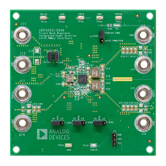
ADP5055-EVALZ PHOTOGRAPH
Rev. 0 | Page 1 of 16
ADP5055-EVALZ
GENERAL DESCRIPTION
This user guide describes the evaluation of the ADP5055 and
includes a detailed schematic and printed circuit board (PCB)
layouts.
The ADP5055-EVALZ features the ADP5055, which combines
three high performance buck regulators in a 43-terminal land
grid array (LGA) to meet the demanding performance and
board space requirements. The ADP5055-EVALZ connects to
input voltages up to 18 V directly, without any preregulators.
The ADP5055 includes a PMBus®-compatible serial interface
and the ADP5055-EVALZ can be used with an external USB
dongle and graphical user interface (GUI) software to evaluate
the power management functionalities and to read back system
status.
Full details on the device are provided in the ADP5055 data
sheet, available from Analog Devices, Inc. Consult this data
sheet in conjunction with this user guide when evaluating the
ADP5055.
Figure 1.
User Guide
UG-1930
Advertisement
Table of Contents

Related Manuals for Analog Devices ADP5055-EVALZ


Summary of Contents for Analog Devices ADP5055-EVALZ
-
Page 1: Features
Frequency synchronization input or output USB dongle and GUI software support The ADP5055 includes a PMBus®-compatible serial interface and the ADP5055-EVALZ can be used with an external USB HARDWARE REQUIREMENTS dongle and graphical user interface (GUI) software to evaluate USB to I... -
Page 2: Table Of Contents
Power Input Jumpers ..............3 Evaluating Efficiency ..............9 J_SYNC Jumper (SYNC/MODE) ..........3 Modifying the ADP5055-EVALZ ..........10 Input Power Source ..............3 Evaluation Board Schematic and Artwork ........12 Output Load .................. 3 Ordering Information .............. -
Page 3: Evaluation Board Hardware
EVALUATION BOARD HARDWARE The ADP5055-EVALZ is fully assembled and tested. Before INPUT POWER SOURCE applying power to the ADP5055-EVALZ, follow the procedures Use the following steps to connect the ADP5055-EVALZ to the in this section. input power source: ENABLE JUMPERS... -
Page 4: Input And Output Voltmeters
Ensure that the voltmeters are connected to the appropriate (PVIN1, PVIN2, and PVIN3) is within the 4.5 V to 18 V ADP5055-EVALZ terminals and not to the load or power range. In addition, shunt the S1 and S2 jumpers to use the sources themselves. -
Page 5: Evaluation Board Software
ADP5055 through the PMBus serial interface. Ensure that the ADP5055-EVALZ is not connected to the USB port of the PC before starting the software installation. INSTALLING THE GUI SOFTWARE To install the ADP5055_GUI software on the PC, take the... -
Page 6: Installing The Adi Sdp Drivers
ADP5055-EVALZ User Guide Choose the components to install. The PreRequisites INSTALLING THE ADI SDP DRIVERS components are enough only for the ADP5055-EVALZ For the PC to communicate with the USB to I C dongle (USB- to use the USB-SDP-CABLEZ dongle. - Page 7 ADP5055-EVALZ User Guide UG-1930 Click Close when the installation is complete. To verify that the USB-SDP-CABLEZ installed properly, open the Device Manager on the PC. With the USB-SDP- CABLEZ dongle connected to PC, verify that the USB- SDP-CABLEZ appears under the ADI Development Tools, as shown in Figure 11.
-
Page 8: Use The Adp5055 Gui Software
ADP5055_GUI software to evaluate the ADP5055_GUI. If the program starts properly, and the advanced functionalities through the PMBus serial interface. ADP5055-EVALZ is detected, the ADP5055 GUI appears as Besides the power supply, the following items are also necessary shown in Figure 13. -
Page 9: Measuring Evaluation Board Performance
ADP5055-EVALZ User Guide UG-1930 MEASURING EVALUATION BOARD PERFORMANCE MEASURING THE OUTPUT VOLTAGE RIPPLE OF EVALUATING THE SYNCHRONIZATION INPUT OR THE BUCK REGULATOR OUTPUT To observe the output voltage ripple of Channel 1, place an The SYNC/MODE pin can be configured as the clock output by... -
Page 10: Modifying The Adp5055-Evalz
Channel 1 and Channel 2 are configured as individual outputs The output voltage (VOUTx) of the three buck regulators are on the ADP5055-EVALZ by default. To configure Channel 1 set through external resistor dividers, as shown in Figure 16, for and Channel 2 to operate in interleaved parallel single output Channel 1. - Page 11 ADP5055-EVALZ User Guide UG-1930 Enabling the Dynamic Voltage Scaling (DVS) The ADP5055 provides a DVS function for Channel 1 to Channel 3. These reference voltages can be programmed in real time via the PMBus serial interface in Register 0xDC (DVS_LIM1) to Register 0xDE (DVS_LIM3).
-
Page 12: Evaluation Board Schematic And Artwork
UG-1930 ADP5055-EVALZ User Guide EVALUATION BOARD SCHEMATIC AND ARTWORK Figure 18. ADP5055-EVALZ Evaluation Board Schematic Rev. 0 | Page 12 of 16 Arrow.com. Arrow.com. Arrow.com. Arrow.com. Arrow.com. Arrow.com. Arrow.com. Arrow.com. Arrow.com. Arrow.com. Arrow.com. Arrow.com. Downloaded from Downloaded from Downloaded from... - Page 13 ADP5055-EVALZ User Guide UG-1930 Figure 19. ADP5055-EVALZ Top Layer, Recommended Layout Figure 20. ADP5055-EVALZ Second Layer, Recommended Layout Rev. 0 | Page 13 of 16 Arrow.com. Arrow.com. Arrow.com. Arrow.com. Arrow.com. Arrow.com. Arrow.com. Arrow.com. Arrow.com. Arrow.com. Arrow.com. Arrow.com. Arrow.com. Downloaded from...
- Page 14 UG-1930 ADP5055-EVALZ User Guide Figure 21. ADP5055-EVALZ Third Layer, Recommended Layout Figure 22. ADP5055-EVALZ Bottom Layer, Recommended Layout Rev. 0 | Page 14 of 16 Arrow.com. Arrow.com. Arrow.com. Arrow.com. Arrow.com. Arrow.com. Arrow.com. Arrow.com. Arrow.com. Arrow.com. Arrow.com. Arrow.com. Arrow.com. Arrow.com. Downloaded from...
-
Page 15: Ordering Information
ADP5055-EVALZ User Guide UG-1930 ORDERING INFORMATION BILL OF MATERIALS Table 4. Qty. Reference Designator Description Manufacturer Part Number Ceramic capacitor, 4.7 μF, X6S, 25 V, Murata GRM188C81E475KE11 10%, 0603 Ceramic capacitor, 4.7 μF, X6S, 6.3 V, Murata GRM155C80J475MEAA 20%, 0402... - Page 16 By using the evaluation board discussed herein (together with any tools, components documentation or support materials, the “Evaluation Board”), you are agreeing to be bound by the terms and conditions set forth below (“Agreement”) unless you have purchased the Evaluation Board, in which case the Analog Devices Standard Terms and Conditions of Sale shall govern. Do not use the Evaluation Board until you have read and agreed to the Agreement.
Need help?
Do you have a question about the ADP5055-EVALZ and is the answer not in the manual?
Questions and answers