Table of Contents
Advertisement
Quick Links
One Technology Way • P.O. Box 9106 • Norwood, MA 02062-9106, U.S.A. • Tel: 781.329.4700 • Fax: 781.461.3113 • www.analog.com
Evaluating the ADP5140 Power Management IC for Automotive Application
FEATURES
Fully featured evaluation board for the ADP5140
Compact solution size
4-layer, high glass transition temperature (T
superior thermal performance
Connections through vertical, printed circuit, tail pin headers
Supply voltage: 3.5 V to 4.1 V (3.7 V typical)
Adjustable output for Buck2 and Buck3 regulators
Fixed output for Buck1, Buck4, boost, and all LDO regulators
Fixed start-up sequence
Voltage monitor and watchdog function
RESET , FAULT , and STATUS outputs
SPI communication protocol
EVALUATION KIT CONTENTS
ADP5140-EVALZ
USB-SDP-CABLEZ serial interface cable
ADP5140 GUI software
DOCUMENT NEEDED
ADP5140 data sheet
SOFTWARE NEEDED
ADP5140 GUI software
EQUIPMENT NEEDED
DC power supply
Electronic load
Oscilloscope
PLEASE SEE THE LAST PAGE FOR AN IMPORTANT
WARNING AND LEGAL TERMS AND CONDITIONS.
GENERAL DESCRIPTION
The ADP5140-EVALZ provides a complete and compact solution
that allows users to evaluate the performance of the
) PCB for
a near ideal printed circuit board (PCB) layout.
G
The main device on the ADP5140-EVALZ, the ADP5140,
integrates four high performance, synchronous step-down buck
regulators (Buck1 to Buck4), one boost regulator, and seven
low noise low dropout (LDO) regulators (LDO1 to LDO7).
Each voltage rail is monitored internally and any fault event is
reported to the system through the RESET pin, FAULT pin,
and STATUS pin.
The ADP5140-EVALZ has enable and sequence controls for all
regulators that allow every voltage rail to start up with a fixed
sequence.
The ADP5140-EVALZ has a serial peripheral interface (SPI) for
system control and diagnostics. A dedicated graphical user
interface (GUI) software is associated with the ADP5140-EVALZ
for flexible evaluation of the ADP5140.
For full details on the ADP5140, see the ADP5140 data sheet,
which must be consulted in conjunction with this user guide
when using the ADP5140-EVALZ.
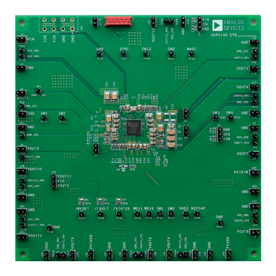
EVALUATION BOARD PHOTOGRAPH
Figure 1. ADP5140-EVALZ Evaluation Board
Rev. 0 | Page 1 of 10
ADP5140-EVALZ
User Guide
UG-1861
ADP5140
with
Advertisement
Table of Contents

Subscribe to Our Youtube Channel
Related Manuals for Analog Devices ADP5140-EVALZ


Summary of Contents for Analog Devices ADP5140-EVALZ
-
Page 1: Features
Voltage monitor and watchdog function and STATUS pin. RESET , FAULT , and STATUS outputs SPI communication protocol The ADP5140-EVALZ has enable and sequence controls for all regulators that allow every voltage rail to start up with a fixed EVALUATION KIT CONTENTS sequence. -
Page 2: Table Of Contents
UG-1861 ADP5140-EVALZ User Guide TABLE OF CONTENTS Features ....................1 Powering Up the ADP5140-EVALZ ...........3 Evaluation Kit Contents ..............1 Measuring Evaluation Board Performance ........3 Document Needed ................1 Software Installation ..............4 Software Needed ................1 Quick Setup ..................4 Equipment Needed ................1 ADP5140 GUI Introduction ............5... -
Page 3: Using The Evaluation Board
Before applying power to the ADP5140-EVALZ, take the the ADP5140-EVALZ and not to the load or the power source. following steps: If the voltmeters are not connected directly to the ADP5140-... -
Page 4: Software Installation
Keeping the Turn on the dc power source. ground length of the oscilloscope probe as short as possible Start the GUI on the PC. The ADP5140-EVALZ is ready allows the true ripple to be measured. for SPI communication. -
Page 5: Adp5140 Gui Introduction
RESET pin, FAULT pin, and STATUS pin if any fault occurs (see Figure 7). When the ADP5140-EVALZ is powered up and the USB-SDP- CABLEZ is connected properly to the ADP5140-EVALZ, SDP appears in the Device Type text box in the GUI Device Info window (see Figure 4). -
Page 6: Evaluation Board Schematic And Artwork
UG-1861 ADP5140-EVALZ User Guide EVALUATION BOARD SCHEMATIC AND ARTWORK Figure 9. ADP5140-EVALZ Schematic Rev. 0 | Page 6 of 10... - Page 7 ADP5140-EVALZ User Guide UG-1861 Figure 10. Layer 1, Component Side Figure 11. Layer 3, Power Plane Rev. 0 | Page 7 of 10...
- Page 8 UG-1861 ADP5140-EVALZ User Guide Figure 12. Layer 2, Ground Plane Figure 13. Layer 4, Bottom Side Rev. 0 | Page 8 of 10...
-
Page 9: Ordering Information
R15 to R18, R29 Optional resistors, 0603 Vishay Dale Optional TP1 to TP41, TP44 to 1-position header connectors, through-hole, gold Wurth 61300111121 TP48 Power management IC for automotive application Analog Devices, Inc. ADP5140WFSACCZ-R7 Rev. 0 | Page 9 of 10... - Page 10 By using the evaluation board discussed herein (together with any tools, components documentation or support materials, the “Evaluation Board”), you are agreeing to be bound by the terms and conditions set forth below (“Agreement”) unless you have purchased the Evaluation Board, in which case the Analog Devices Standard Terms and Conditions of Sale shall govern. Do not use the Evaluation Board until you have read and agreed to the Agreement.
Need help?
Do you have a question about the ADP5140-EVALZ and is the answer not in the manual?
Questions and answers