Table of Contents
Advertisement
Quick Links
One Technology Way • P.O. Box 9106 • Norwood, MA 02062-9106, U.S.A. • Tel: 781.329.4700 • Fax: 781.461.3113 • www.analog.com
Evaluating the
ADP5062 FEATURES
Input voltage 4.0 V to 6.7 V
High current terminals for
ADP5062
(VINx), system voltage (ISO_Sx), and battery voltage
(ISO_Bx) pins
ADP5062
operation configurable via I
Evaluation software included
PACKAGE CONTENTS
ADP5062CP-EVALZ evaluation board
Evaluation CD: ADP5062 evaluation software installer
HARDWARE REQUIREMENTS
USB-to-serial-I/O interface USB-SDP-CABLEZ (The USB-SDP-
CABLEZ is not supplied in the evaluation kit and should be
ordered separately from Analog Devices, Inc.)
SOFTWARE REQUIREMENTS
Analog Devices ADP5062 SDP evaluation software
PLEASE SEE THE LAST PAGE FOR AN IMPORTANT
WARNING AND LEGAL TERMS AND CONDITIONS.
ADP5062
Linear Li-Ion Battery Charger with Power
Path and USB Compatibility in LFCSP
power connection
2
C interface
ADP5062
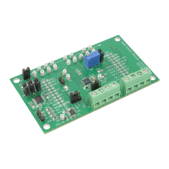
EVALUATION BOARD
Figure 1.
Rev. 0 | Page 1 of 15
Evaluation Board User Guide
GENERAL DESCRIPTION
The
ADP5062
charger evaluation system is composed of an
evaluation board, an USB A to USB micro B cable and an USB
A adapter board. All evaluation board functions and circuits are
2
controlled via one I
C bus connector. The I
with the
ADP5062
directly, and the digital input/output signals
are controlled through an on-board input/output expander
2
circuit on the I
C bus. The evaluation board also features a 3.4
V regulator for VDDIO generation. The board contains jumpers
and numerous test points for easy evaluation.
The ADP5062CP-EVALZ evaluation kit contains a CD with the
ADP5062 GUI 3v0 installer. Use the GUI in conjunction with
the USB-SDP-CABLEZ, USB to Serial I/O Interface.
Full performance details are provided in the
sheet, and the
ADP5062
data sheet should be consulted in
conjunction with this user guide.
UG-500
2
C bus interfaces
ADP5062
data
Advertisement
Table of Contents

Subscribe to Our Youtube Channel
Related Manuals for Analog Devices ADP5062


Summary of Contents for Analog Devices ADP5062
-
Page 1: Adp5062 Features
Evaluation CD: ADP5062 evaluation software installer The ADP5062CP-EVALZ evaluation kit contains a CD with the HARDWARE REQUIREMENTS ADP5062 GUI 3v0 installer. Use the GUI in conjunction with the USB-SDP-CABLEZ, USB to Serial I/O Interface. USB-to-serial-I/O interface USB-SDP-CABLEZ (The USB-SDP- CABLEZ is not supplied in the evaluation kit and should be... -
Page 2: Table Of Contents
Evaluation Board Software .............. 3 Termination Voltage and End of Charge (EOC) Current ..9 Installing ADP5062 Evaluation Software ........3 THR Input and JEITA Settings ..........10 Using the Software Graphical User Interface (GUI) ....4 Schematic Diagram ................ -
Page 3: Evaluation Board Software
INSTALLING ADP5062 EVALUATION SOFTWARE the ADP5062-EVALZ setup CD and run the Setup.exe file by Before installing the ADP5062 evaluation software, the drivers for following the steps provided in the software installation instruction the USB-SDP-CABLEZ must be installed. The software and the document. -
Page 4: Using The Software Graphical User Interface (Gui)
Opr Control & Status tab. Complete the following steps to use the board: Before running the software, ensure that the Analog Devices USB-SDP-CABLEZ to the USB port of the PC. Connect a 5 V power supply to VIN_F. -
Page 5: Setting Interrupts
Evaluation Board User Guide UG-500 SETTING INTERRUPTS SETTING TIMERS ADP5062 includes several interrupt flags to inform the The default settings of the timers are shown in Figure 3. Changing system microcontroller of a status change in the corresponding the timer settings can be done by clicking items in the Timer charger function. -
Page 6: Direct Register Read And Write
UG-500 Evaluation Board User Guide Figure 4. ADP5062 Evaluation Software GUI, Register R/W Tab address in the Sub Address for READ and WRITE (0x00) box, DIRECT REGISTER READ AND WRITE and then press ENTER. Click READ to read the binary data, or It is possible to read and write the content of each register using click WRITE to write the binary data. -
Page 7: Evaluation Board Overview
ISO_S_F ISO_S_F BAT_SNS ISO_B_F GND VIN_F R14 R1 VCO_LDO Figure 5. ADP5062 LFCSP Demo Board Typical Operation Setup. INPUT CURRENT TYPICAL OPERATION Measuring Total Input Current (I The typical test setup for the ADP5062 charger consists of a dc When measuring VINx input quiescent currents, take into... -
Page 8: Trickle Charge Current
3.6 V on SMU B ISO_B Enable charging by setting Register 0x07, bit D0 (EN_CHG), high Confirm the ADP5062 charging mode: The Battery Status indicator on the GUI must show BAT_SNS > Vweak (see Figure 2). ... -
Page 9: Fast Charge Current
Repeat Step 9 to Step 12 to Simulator evaluate different settings. ADP5062 fast charge constant voltage (CV) regulation is optimized for batteries with series resistance in the 100 mΩ to 250 mΩ range. When using a SMU or a battery simulator... -
Page 10: Thr Input And Jeita Settings
11. The THR-pin status indicator in the GUI must show BatCold, BatCool, Thermistor OK, BatWarm, or BatHot The THR input of the ADP5062 evaluation board is equipped when adjusting the trimmer resistance from 50 kΩ to 0 Ω. with the 50 kΩ trimmer resistor (R3) and jumper J10. When using an actual Li-Ion NTC thermistor terminal, configure the board according to Error! Reference source not found.. -
Page 11: Schematic Diagram
DIG_IO2 ISO_B2 BAT_SNS ISO_B1 VDDIO N.A. N.A. N.A. DIG_IO1 VIN1 ISO_S3 SY S_EN VIN2 ISO_S2 pca9557dbg4 VIN3 ISO_S1 ADP5062 QFN20 SN11 RESET* ILED 22uF 100n 22uF SYM 1 OF 1 TP11 TP12 TP13 TP14 TP15 TP17 TP19 TP10 TP16 TP18... -
Page 12: Ordering Information
Resistor, 0.150 Ω, 1%, 0805, SMD Rohm MCR10EZHFLR150 TP1 to TP20 Test point, test header, 1.0 mm hole Vero Technologies 20-2137 Analog Devices, Inc. ADP1720ARMZ-R7 ADP1720 50 mA high voltage, micropower linear regulator, 8-lead MSOP ADP5062 Linear Li-Ion Battery Charger with Power Analog Devices, Inc. - Page 13 Evaluation Board User Guide UG-500 NOTES Rev. 0 | Page 13 of 15...
- Page 14 UG-500 Evaluation Board User Guide NOTES Rev. 0 | Page 14 of 15...
- Page 15 By using the evaluation board discussed herein (together with any tools, components documentation or support materials, the “Evaluation Board”), you are agreeing to be bound by the terms and conditions set forth below (“Agreement”) unless you have purchased the Evaluation Board, in which case the Analog Devices Standard Terms and Conditions of Sale shall govern. Do not use the Evaluation Board until you have read and agreed to the Agreement.
Need help?
Do you have a question about the ADP5062 and is the answer not in the manual?
Questions and answers