Table of Contents
Advertisement
Quick Links
One Technology Way • P.O. Box 9106 • Norwood, MA 02062-9106, U.S.A. • Tel: 781.329.4700 • Fax: 781.461.3113 • www.analog.com
AD8450/ADP1972
FEATURES
Fully functional Li-Ion cell formation and testing similar to
real-world manufacturing equipment
Ability to charge and discharge batteries under constant
current (CC) and constant voltage (CV) control
Energy recycling from discharging battery into dc bus
Full featured system evaluation board based on the
AD8450
and
ADP1972
PC software for control and monitoring of system
parameters
Compatible with the system demonstration platform,
SDP-S (EVAL-SDP-CS1Z)
EQUIPMENT NEEDED
Bench power supply, 12 V dc (current depending on desired
battery charge rate)
Test battery
EVALUATION KIT CONTENTS
Analog control board
Power stage board
SDP-S board for data transfer to PC
Standard USB A to Mini-B USB cable
Printed user guide
Evaluation kit software CD
Business card with Analog Devices, Inc., website address for
software and documentation
HARDWARE REQUIREMENTS
Bench power supply, 12 V dc (current depending on desired
battery charge rate)
Test battery or electronic load
PC running Windows 7
WARNING
When testing this system with lithium-ion (Li-Ion) batteries,
take care not to overcharge or overdischarge the batteries, or to
sink/source more than the maximum current recommended by
the manufacturer of the battery. Exceeding these ratings not
only damages the battery, but can also cause it to explode or
catch fire.
PLEASE SEE THE LAST PAGE FOR AN IMPORTANT
WARNING AND LEGAL TERMS AND CONDITIONS.
AD8450-EVALZ/ADP1972-EVALZ User Guide
Battery Testing and Formation Evaluation Board
Rev. 0 | Page 1 of 33
GENERAL DESCRIPTION
The
AD8450-EVALZ/ADP1972-EVALZ
starting point for users building battery formation and test
equipment based on the Analog Devices
analog front end and controller and the
pulse-width modulation (PWM) controller. The system includes
an analog control board and a power stage board.
In addition to the
AD8450
and ADP1972, the analog control
board also includes an
AD5689R
analog converter (DAC) to set the current and voltage set points,
and an
AD7173-8
24-bit, Σ-Δ analog-to-digital converter (ADC)
to monitor the battery voltage and current.
The board includes built-in voltage regulators so that it can be
powered either from the power stage board or directly from a
12 V dc through a screw terminal connector.
The analog control board connects to the Analog Devices
system demonstration platform—serial (SDP-S) board through
a 120-pin connector. The SDP-S board connects to the user
interface software through the USB port, allowing the user to
set the current and voltage set point as well as the mode of
operation (charge/discharge). In addition, the user can monitor
the battery voltage and current by reading the data output from
the AD7173-8.
The analog control board connects to the power stage board
through a 32-pin header. This modular approach allows the
user to design and test their own power stage boards, designed
for the current output range in their end applications, with the
analog control board of this reference design.
The power stage board supports charge and discharge currents
of up to 20 A. It includes the power MOSFETs, inductor, and
input and output capacitors required to implement a buck or
boost regulator, depending on the operating mode.
Full specifications on the
ADP1972
the product data sheets, which should be consulted in conjunction
with this user guide when working with the evaluation kit.
The
AD8451
can also be installed in the
minimal changes.
UG-845
evaluation kit is a good
AD8450
precision
ADP1972
buck or boost
16-bit, precision digital-to-
and
AD8450
are available in
AD8450
socket with
Advertisement
Table of Contents

Related Manuals for Analog Devices AD8450-EVALZ


Summary of Contents for Analog Devices AD8450-EVALZ
-
Page 1: Features
12 V dc through a screw terminal connector. Test battery The analog control board connects to the Analog Devices system demonstration platform—serial (SDP-S) board through EVALUATION KIT CONTENTS a 120-pin connector. The SDP-S board connects to the user... -
Page 2: Table Of Contents
UG-845 AD8450-EVALZ/ADP1972-EVALZ User Guide TABLE OF CONTENTS Features ....................1 Evaluation Board Software ...............7 Equipment Needed ................1 Installing the Software ..............7 Evaluation Kit Contents ..............1 Installation Steps ................7 Hardware Requirements ..............1 Board Operation and Connection Sequence ......8... -
Page 3: Simplified Evaluation Board Block Diagram
AD8450-EVALZ/ADP1972-EVALZ User Guide UG-845 SIMPLIFIED EVALUATION BOARD BLOCK DIAGRAM POWER BOARD DC_LINK POWER DRIVER ADP2441 ADuM7223 BUS_PWR CS– VS– AGND COMP 12V_AUX POWER BUCK AND BOOST V AND I SENSE ADP7102 PWM CONTROLLER CC AND CV CONTROLLER ADM8829 ADP1972 AD8450... -
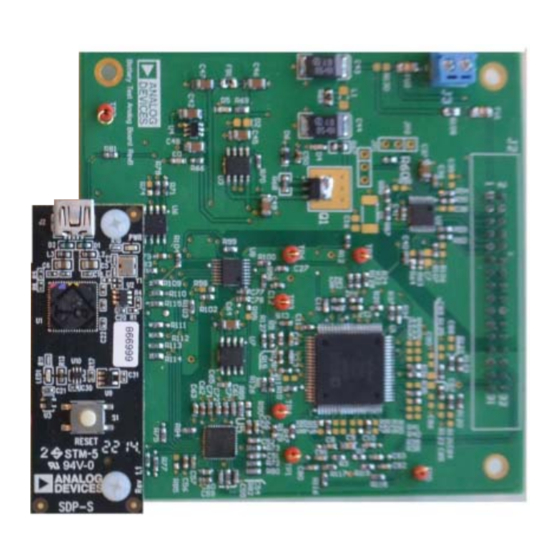
Page 4: Evaluation Board Photograph
UG-845 AD8450-EVALZ/ADP1972-EVALZ User Guide EVALUATION BOARD PHOTOGRAPH Figure 2. Power Stage Board (Left) and Analog Control Board with SDP-S Attached (Right) Rev. 0 | Page 4 of 33... -
Page 5: Evaluation Board Hardware
AD8450-EVALZ/ADP1972-EVALZ User Guide UG-845 EVALUATION BOARD HARDWARE SETTING UP THE EVALUATION SYSTEM SERIAL INTERFACE Figure 26 to Figure 29 show the analog control board schematic, The evaluation system uses the SPI interface on the SDP-S board and Figure 17 shows the power stage board schematic. -
Page 6: Power Stage Board Description
UG-845 AD8450-EVALZ/ADP1972-EVALZ User Guide POWER STAGE BOARD DESCRIPTION ANALOG CONTROL BOARD DESCRIPTION Figure 17 shows the power stage board schematic. The bench The analog control board includes the ADP1972, the AD8450/ power supply connects to the power stage board through the AD8451, a DAC to configure the set points, and an ADC to J2 (+) and J4 (−) banana jacks. -
Page 7: Evaluation Board Software
AD8450-EVALZ/ADP1972-EVALZ User Guide UG-845 EVALUATION BOARD SOFTWARE INSTALLING THE SOFTWARE The evaluation board software can be downloaded from the AD8450, AD8451, and ADP1972 product pages on the Analog Devices website at www.analog.com. Install the software prior to connecting the SDP-S board to the USB port of the PC to ensure that the SDP-S board is recognized when it connects to the PC. -
Page 8: Board Operation And Connection Sequence
Connect an electronic load or battery. Connect the board to the PC with the USB cable. To launch the software, click Start > All Programs > Analog Devices > AD8450 System Demo > AD8450- Figure 9. Choose Install Location (Default Folder Shown) ADP1972 Demo. -
Page 9: Running The Software With The Hardware Connected
Figure 13 displays. Click Select to continue. CONNECTED To run the program, take the following steps: Click Start > All Programs > Analog Devices > AD8450 System Demo > AD8450-ADP1972 Demo. If the SDP-S board is not connected to the USB port when the software is launched, a connectivity error displays (see Figure 12). -
Page 10: Software Operation
UG-845 AD8450-EVALZ/ADP1972-EVALZ User Guide SOFTWARE OPERATION When the software launches, the window shown in Figure 14 mode. Clicking this button changes the power stage configuration opens and the software begins communicating with the analog (the button changes to MODE: DISCHARGE). -
Page 11: Configuration Tab
AD8450-EVALZ/ADP1972-EVALZ User Guide UG-845 Figure 15. Software Main Window During Normal Operation Calibration Controls CONFIGURATION TAB The gain correction and offset controls allow the user to Click Configure System to open the configuration tab (see perform system level calibration. The measurements displayed Figure 16). - Page 12 UG-845 AD8450-EVALZ/ADP1972-EVALZ User Guide Hardware Configuration Controls Sense Resistor (Ohms) is the nominal value of the sense resistor on the power stage board. The default is 0.002 Ω (2 mΩ). As indicated in the main window, the hardware configuration controls must reflect the actual configuration of the power stage...
-
Page 13: Evaluation Board Schematics-Power Stage Board
AD8450-EVALZ/ADP1972-EVALZ User Guide UG-845 EVALUATION BOARD SCHEMATICS—POWER STAGE BOARD Figure 17. Power Stage Board Schematic Rev. 0 | Page 13 of 33... - Page 14 UG-845 AD8450-EVALZ/ADP1972-EVALZ User Guide Table 4. Power Stage Board Bill of Materials Reference Designator Description Manufacturer Part No. C1, C2 0.47 μF/100 V, X7R, MLCC Murata GRM21BR72A474KA73 C3, C7 680 μF/35 V, aluminum electrolytic capacitor Panasonic EEVFK1V681Q C4, C5, C6, C11, C12 10 μF/50 V, X5R, MLCC...
- Page 15 AD8450-EVALZ/ADP1972-EVALZ User Guide UG-845 Figure 18. Power Stage Board Top Silkscreen Figure 19. Power Stage Board Top Layer Rev. 0 | Page 15 of 33...
- Page 16 UG-845 AD8450-EVALZ/ADP1972-EVALZ User Guide Figure 20. Power Stage Board Layer 2 Figure 21. Power Stage Board Layer 3 Rev. 0 | Page 16 of 33...
- Page 17 AD8450-EVALZ/ADP1972-EVALZ User Guide UG-845 Figure 22. Power Stage Board Layer 4 Figure 23. Power Stage Board Layer 5 Rev. 0 | Page 17 of 33...
- Page 18 UG-845 AD8450-EVALZ/ADP1972-EVALZ User Guide Figure 24. Power Stage Board Bottom Layer Figure 25. Power Stage Board Bottom Silkscreen Rev. 0 | Page 18 of 33...
-
Page 19: Evaluation Board Schematics-Analog Control Board
AD8450-EVALZ/ADP1972-EVALZ User Guide UG-845 EVALUATION BOARD SCHEMATICS—ANALOG CONTROL BOARD A G ND A G ND A G ND R116 R117 CS_P I SV P R118 R119 10nF CS_N I SV N A G ND A G ND A G ND... - Page 20 UG-845 AD8450-EVALZ/ADP1972-EVALZ User Guide Figure 27. AD8450 and Compensation Networks Rev. 0 | Page 20 of 33...
- Page 21 AD8450-EVALZ/ADP1972-EVALZ User Guide UG-845 Figure 28. ADP1972 and Local Power Supplies Rev. 0 | Page 21 of 33...
- Page 22 UG-845 AD8450-EVALZ/ADP1972-EVALZ User Guide Figure 29. ADC, DAC, and SDP-S Connector Rev. 0 | Page 22 of 33...
- Page 23 AD8450-EVALZ/ADP1972-EVALZ User Guide UG-845 Table 5. Analog Control Board Bill of Materials Reference Designator Description Manufacturer Part Number C1, C2, C13, C14, C17, C18, C20, C21, C23, Not applicable Not applicable Not applicable C24, C38, C39, C84 to C86, C88 to C90 C12, C27, C36, C41, C57, C60, C63, C65, C66, Ceramic capacitor, 0603, 1.0 μF, 25 V...
- Page 24 UG-845 AD8450-EVALZ/ADP1972-EVALZ User Guide Figure 30. Analog Control Board Top Silkscreen Rev. 0 | Page 24 of 33...
- Page 25 AD8450-EVALZ/ADP1972-EVALZ User Guide UG-845 Figure 31. Analog Control Board Top Layer Rev. 0 | Page 25 of 33...
- Page 26 UG-845 AD8450-EVALZ/ADP1972-EVALZ User Guide Figure 32. Analog Control Board Layer 2 (Ground) Rev. 0 | Page 26 of 33...
- Page 27 AD8450-EVALZ/ADP1972-EVALZ User Guide UG-845 Figure 33. Analog Control Board Layer 3 Rev. 0 | Page 27 of 33...
- Page 28 UG-845 AD8450-EVALZ/ADP1972-EVALZ User Guide Figure 34. Analog Control Board Layer 4 Rev. 0 | Page 28 of 33...
- Page 29 AD8450-EVALZ/ADP1972-EVALZ User Guide UG-845 Figure 35. Analog Control Board Layer 5 (Power) Rev. 0 | Page 29 of 33...
- Page 30 UG-845 AD8450-EVALZ/ADP1972-EVALZ User Guide Figure 36. Analog Control Board Bottom Layer Rev. 0 | Page 30 of 33...
- Page 31 AD8450-EVALZ/ADP1972-EVALZ User Guide UG-845 Figure 37. Analog Control Board Bottom Silkscreen Rev. 0 | Page 31 of 33...
-
Page 32: Troubleshooting
UG-845 AD8450-EVALZ/ADP1972-EVALZ User Guide TROUBLESHOOTING SOFTWARE HARDWARE To troubleshoot the software, take the following steps: To troubleshoot the hardware, take the following steps: Always install the software prior to connecting the If the software does not read any data back, check that the hardware to the PC. -
Page 33: Products On This Evaluation System
By using the evaluation board discussed herein (together with any tools, components documentation or support materials, the “Evaluation Board”), you are agreeing to be bound by the terms and conditions set forth below (“Agreement”) unless you have purchased the Evaluation Board, in which case the Analog Devices Standard Terms and Conditions of Sale shall govern. Do not use the Evaluation Board until you have read and agreed to the Agreement.
Need help?
Do you have a question about the AD8450-EVALZ and is the answer not in the manual?
Questions and answers