Table of Contents
Advertisement
Quick Links
One Technology Way • P.O. Box 9106 • Norwood, MA 02062-9106, U.S.A. • Tel: 781.329.4700 • Fax: 781.461.3113 • www.analog.com
Evaluating the
FEATURES
Full featured evaluation board for the
Compact solution size
4-layer high glass transition temperature (T
superior thermal performance
Convenient connections through vertical printed circuit tail
pin headers
Supply voltage
2.75 V to 6.0 V for PVINx
Mode option to select manual or sequence enable
Mode option to select PSM or FPWM operation
Programmable switching frequency from 500 kHz to 2.5 MHz
Frequency synchronization input or output
DOCUMENT NEEDED
ADP5014
data sheet
EQUIPMENT NEEDED
DC power supply
Voltmeter
Ammeter
Load resistors or electrical load
Oscilloscope
PLEASE SEE THE LAST PAGE FOR AN IMPORTANT
WARNING AND LEGAL TERMS AND CONDITIONS.
ADP5014
4-Channel Power Management Unit
ADP5014
) PCB for
G
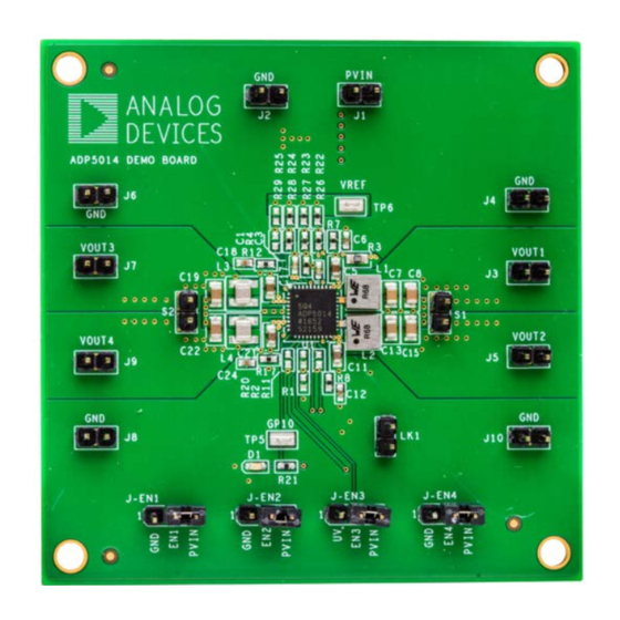
ADP5014-EVALZ PHOTOGRAPH
Figure 1.
Rev. 0 | Page 1 of 11
ADP5014-EVALZ
GENERAL DESCRIPTION
This user guide describes the evaluation of the
includes detailed schematics and printed circuit board (PCB)
layouts.
The ADP5014-EVALZ evaluation board combines four high
performance buck regulators in a 40-lead LFCSP package to
meet the demanding performance and board space
requirements.
Full details on the
ADP5014
ADP5014
data sheet, available from Analog Devices, Inc.
Consult the data sheet in conjunction with this user guide
when working with this evaluation board.
User Guide
UG-1137
ADP5014
regulator are provided in the
and
Advertisement
Table of Contents

Related Manuals for Analog Devices ADP5014-EVALZ


Summary of Contents for Analog Devices ADP5014-EVALZ
-
Page 1: Features
4-layer high glass transition temperature (T ) PCB for superior thermal performance The ADP5014-EVALZ evaluation board combines four high Convenient connections through vertical printed circuit tail performance buck regulators in a 40-lead LFCSP package to pin headers meet the demanding performance and board space Supply voltage requirements. -
Page 2: Table Of Contents
Modifying the Board ..............5 Equipment Needed ................1 Evaluation Board Schematic and Artwork ........7 General Description ................. 1 Schematic..................7 ADP5014-EVALZ Photograph ............1 PCB Layout ..................8 Revision History ................2 Ordering Information ..............10 Using the Evaluation Board ............. 3 Bill of Materials ................ -
Page 3: Using The Evaluation Board
Using Buck 1 as an example, connect the positive terminal of the load to J3 (VOUT1) of the evaluation board and connect the The ADP5014-EVALZ evaluation board is supplied fully negative terminal of the load to J4 (GND). assembled and tested. Before applying power to the evaluation Input and Output Voltmeter board, follow the procedures in this section. -
Page 4: Measuring Evaluation Board Performance
UG-1137 ADP5014-EVALZ User Guide PVIN: 2.75V TO 6.0V VREF VOUT3: 1.8V AT 2A VOUT1: 1.0V AT 4A VOUT4: 3.3V AT 2A VOUT2: 1.5V AT 4A GPIO Figure 2. Evaluation Board Connection Diagram MEASURING EVALUATION BOARD Measuring Efficiency PERFORMANCE The efficiency, η, is measured by comparing the input power with the output power. -
Page 5: Modifying The Board
To observe the output voltage ripple, place the oscilloscope probe across the output capacitor with the probe ground lead connected The output voltage of Buck 1 of the ADP5014-EVALZ evaluation to the negative (−) capacitor terminal and the probe tip placed at board is preset to 1 V. - Page 6 The value of Short the S1 jumper. R2 on the ADP5014-EVALZ evaluation board is 0 Ω. To change Change R1 = 21.5 kΩ in the CFG1 pin setting. the configuration, replace the R2 resistor at the CFG2 pin with a Remove R8 and C12 from the COMP2 pin.
-
Page 7: Evaluation Board Schematic And Artwork
ADP5014-EVALZ User Guide UG-1137 EVALUATION BOARD SCHEMATIC AND ARTWORK SCHEMATIC Figure 4. Evaluation Board Schematic for the ADP5014-EVALZ Rev. 0 | Page 7 of 11... -
Page 8: Pcb Layout
UG-1137 ADP5014-EVALZ User Guide PCB LAYOUT Figure 5. Layer 1, Top Side Figure 6. Layer 3, Power Plane Rev. 0 | Page 8 of 11... - Page 9 ADP5014-EVALZ User Guide UG-1137 Figure 7. Layer 2, Ground Plane Figure 8. Layer 4, Bottom Side Rev. 0 | Page 9 of 11...
-
Page 10: Ordering Information
UG-1137 ADP5014-EVALZ User Guide ORDERING INFORMATION BILL OF MATERIALS Table 3. Bill of Materials for the ADP5014-EVALZ Reference Designator Description Part Number/Vendor C1, C3 Capacitor, 0.47 μF, 10 V, 0402 GRM155R61A474KE15D/Murata C2, C4 Capacitor, 47 μF, 16 V,1210 GRM32ER61C476KE15L/Murata C5, C11, C17, C21 Capacitor, 10 μF, 16 V, 0603... - Page 11 By using the evaluation board discussed herein (together with any tools, components documentation or support materials, the “Evaluation Board”), you are agreeing to be bound by the terms and conditions set forth below (“Agreement”) unless you have purchased the Evaluation Board, in which case the Analog Devices Standard Terms and Conditions of Sale shall govern. Do not use the Evaluation Board until you have read and agreed to the Agreement.
- Page 12 Mouser Electronics Authorized Distributor Click to View Pricing, Inventory, Delivery & Lifecycle Information: Analog Devices Inc. ADP5014-EVALZ...
Need help?
Do you have a question about the ADP5014-EVALZ and is the answer not in the manual?
Questions and answers