Table of Contents
Advertisement
Quick Links
ACP VC1 EU/MK • Setup Guide
The Extron ACP VC1 EU/MK Audio Control Panel is a fully configurable control interface for use with any Extron ACP-enabled
device.
Each ACP VC1 EU/MK includes two ACP ports, which support power and communication between the host device and the
ACP VC1 EU/MK. Up to eight ACP panels can be used per host device for more demanding control needs.
NOTE:
The ACP VC1 EU front and rear panels are identical to those of the ACP VC1 MK. The only difference is the shape of
the plastic faceplate attached to the front of the device. The panels function identically.
Planning System Installation
When planning an ACP system installation, consider how many ACP panels to use, maximum cable distance, and mounting (see
the ACP VC1 EU and ACP VC1 MK product pages at
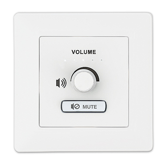
Front and Rear Panel Features
VOLUME
VOLUME
A A
B B
MUTE
MUTE
Figure 1.
ACP VC1 EU/MK
Front Panel Rotary Volume Knob
A
Front Panel Button
B
ACP Ports (2)
C
Installation
Step 1: Get Ready
Use the following checklist to prepare for installation:
…
Download and install the latest software, firmware, and device drivers needed to configure the host device and the
connected ACP devices (see the host device user guide, available at www.extron.com, for details regarding software and
drivers).
…
Obtain cables, mounting hardware, and any other supplies required for the installation.
All manuals and user guides at all-guides.com
www.extron.com
C C
F F
Connection Status LED
D
Reset Button
E
Bus ID DIP Switches
F
for more information regarding the ACP VC1 EU/MK).
E E
1
Advertisement
Table of Contents

Related Manuals for Extron electronics ACP VCI EU/MK


Summary of Contents for Extron electronics ACP VCI EU/MK
- Page 1 All manuals and user guides at all-guides.com ACP VC1 EU/MK • Setup Guide The Extron ACP VC1 EU/MK Audio Control Panel is a fully configurable control interface for use with any Extron ACP-enabled device. Each ACP VC1 EU/MK includes two ACP ports, which support power and communication between the host device and the ACP VC1 EU/MK.
-
Page 2: Step 2: Prepare The Installation Site
All manuals and user guides at all-guides.com ACP VC1 EU/MK • Setup Guide (Continued) Step 2: Prepare the Installation Site ATTENTION: • Installation and service must be performed by authorized personnel only. • L’installation et l’entretien doivent être effectués par le personnel autorisé uniquement. •... - Page 3 All manuals and user guides at all-guides.com slot in the button plate until the membrane containing the button is free. To replace the button, align the two pegs in the button membrane with the holes located at opposite corners of the empty slot on the back of the button faceplate and push the button forward so it fits in the desired slot (see the figure to the right).
- Page 4 All manuals and user guides at all-guides.com ACP VC1 EU/MK • Setup Guide (Continued) Setting the Bus ID Address Each ACP device in a system must have a unique six-digit binary bus ID. ACP bus Example Addresses IDs are set using the DIP switch assembly on the rear panel of the Bus ID Binary DIP Switch...
- Page 5 All manuals and user guides at all-guides.com ATTENTION: • Always use a power supply supplied or specified by Extron. Use of an unauthorized power supply voids all regulatory compliance certification and may cause damage to the supply and the unit. •...
-
Page 6: Step 6: Configure The System
All manuals and user guides at all-guides.com ACP VC1 EU/MK • Setup Guide (Continued) ACP VC1 EU ACP VC1 EU Rear Panel Rear Panel 3/16" (5 mm) Max. Ground ACP port - Signal on a DMP 128 + Signal Plus Power Input, External Power Supply (optional) Tie drain wires to ground. - Page 7 All manuals and user guides at all-guides.com Step 8: Mounting the ACP VC1 EU/MK Prior to mounting: Feed all device cables through the wall or furniture. NOTE: If the unit is not installed in a mud ring, the plastic spacer must be installed. The spacer positions the unit to allow the plastic faceplate to attach properly and securely.
- Page 8 For information on safety guidelines, regulatory compliances, EMI/EMF compatibility, accessibility, and related topics, see the Extron Safety and Regulatory Compliance Guide on the Extron website. © 2019 Extron Electronics — All rights reserved. www.extron.com 68-3421-50 Rev. A All trademarks mentioned are the property of their respective owners.
Need help?
Do you have a question about the ACP VCI EU/MK and is the answer not in the manual?
Questions and answers