
Related Manuals for Kemppi Master M 353


Summary of Contents for Kemppi Master M 353
- Page 1 Master M 353, 355 Operating manual - EN Master M 353, 355 © Kemppi 1921960 / 2307...
-
Page 2: Table Of Contents
Master M 353, 355 Operating manual - EN CONTENTS 1. General 1.1 Equipment description 1.2 Master M device 1.2.1 Wire feed mechanism 1.3 Master M Cooler cooling unit (optional) 2. Installation 2.1 Installing power source mains plug 2.2 Installing cooling unit (optional) 2.3 Installing equipment on cart (optional) - Page 3 Master M 353, 355 Operating manual - EN 3.4.8 WeldEye with DCM (optional) 3.5 Using remote control 3.6 Changing welding polarity 3.7 Lifting Master M equipment 4. Maintenance 4.1 Daily maintenance 4.2 Periodic maintenance 4.3 Service workshops 4.4 Troubleshooting 4.5 Error codes 4.6 Installing and cleaning power source air filter (optional)
-
Page 4: General
Master M 355 G Master M 355 GM Master M is designed to be used together with Kemppi's Flexlite GX MIG welding guns with euro connector. Master M can be used also for TIG * and MMA ** welding. * TIG welding requires the use of a dedicated Flexlite TX TIG torch with euro connector. - Page 5 While every effort has been made to ensure that the information contained in this guide is accurate and com- plete, no liability can be accepted for any errors or omissions. Kemppi reserves the right to change the spe- cification of the product described at any time without prior notice. Do not copy, record, reproduce or transmit the contents of this guide without prior permission from Kemppi.
-
Page 6: Equipment Description
For more information on acquiring welding programs and additional welding processes, contact your local Kemppi dealer. Subfeeders Subfeeder support can be added with a separate installation kit (contact your Kemppi dealer / service workshop for more information). • SuperSnake GTX subfeeder. - Page 7 Power source air filter • Wire feed cabinet heater. For more information on optional accessories, contact your local Kemppi dealer. EQUIPMENT IDENTIFICATION Serial number Serial number of the device is marked on the rating plate or in another distinctive location on the device. It is important to make correct reference to the serial number of the product when ordering spare parts or making repairs for example.
-
Page 8: Master M Device
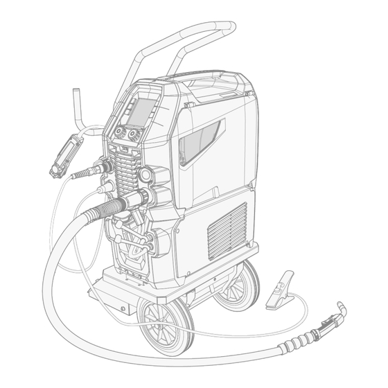
Master M 353, 355 Operating manual - EN 1.2 Master M device Front Transportation handle (also for mechanical lifting when the device is not installed on a cooling unit or cart) Control panel LED work lights with light switch in the middle >>... -
Page 9: Wire Feed Mechanism
Master M 353, 355 Operating manual - EN Mains cable Power switch Rear locking interface >> For locking on top of the cooling unit or on the cart. Inside wire feed cabinet Gas regulating valve (Master M 355) >> For setting the gas flow rate in the device lower than the gas flow rate from the gas supply... - Page 10 Master M 353, 355 Operating manual - EN Outlet guide tube. For replacing the feed rolls, refer to "Installing and replacing feed rolls" on page 26. For replacing the wire guide tubes, refer to "Installing and replacing wire guide tubes" on page 28.
-
Page 11: Master M Cooler Cooling Unit (Optional)
Master M 353, 355 Operating manual - EN 1.3 Master M Cooler cooling unit (optional) Front Cooler container cap Cooling liquid level indicator Cooling liquid circulation button >> Keeping the button pressed activates the pump and circulates the cooling liquid throughout the system. Once released, the pump stops. -
Page 12: Installation
Master M 353, 355 Operating manual - EN 2. INSTALLATION Do not connect the equipment to the mains before the installation is complete. Do not modify the welding equipment in any way, except for the changes and adjustments covered in the man- ufacturer’s instructions. -
Page 13: Installing Power Source Mains Plug
Master M 353, 355 Operating manual - EN 2.1 Installing power source mains plug Only an authorized electrician is allowed to install the mains cable and plug. Do not connect the machine to the mains before the installation is complete. -
Page 14: Installing Cooling Unit (Optional)
Master M 353, 355 Operating manual - EN 2.2 Installing cooling unit (optional) The Master M cooling unit must be installed by authorized service personnel. Tools needed: Remove the small connector cover in the rear of the power source. Route the cooling unit's connection cables so that they remain accessible through the next steps. - Page 15 Master M 353, 355 Operating manual - EN Fix the units together with two screws (M5x12) in the front and two screws (M5x12) in the rear. Connect the cooling unit cables. Replace the small connector cover. © Kemppi 1921960 / 2307...
-
Page 16: Installing Equipment On Cart (Optional)
Master M 353, 355 Operating manual - EN 2.3 Installing equipment on cart (optional) Master M has four transport unit options: a 4-wheel cart with a gas bottle rack (P45MT), a 4-wheel cart without a gas bottle rack (P43MT), a 2-wheel cart with a gas bottle rack (T25MT) and a 2-wheel cart without a gas bottle rack (T35A). - Page 17 Master M 353, 355 Operating manual - EN T35A 2-wheel cart: The cart must be in horizontal position during welding. For lifting the Master M equipment, refer to "Lifting Master M equipment" on page 54. © Kemppi 1921960 / 2307...
-
Page 18: Connecting Welding Gun
Operating manual - EN 2.4 Connecting welding gun Master M is designed to be used with the Kemppi Flexlite GX welding guns. For the Flexlite GX operating instructions, refer to userdoc.kemppi.com. Always check that the wire liner, contact tip and gas nozzle are suitable for the job. -
Page 19: Connecting Earth Return Cable
Master M 353, 355 Operating manual - EN 2.5 Connecting earth return cable Connect the earth return cable to the welding machine. © Kemppi 1921960 / 2307... -
Page 20: Installing Remote Control (Optional)
Master M 353, 355 Operating manual - EN 2.6 Installing remote control (optional) Remote controls are optional. To enable remote operation, connect the remote control device to the Master M welding equipment. The remote control mode can be set and adjusted in the control panel settings ("Control panel: System set- tings"... -
Page 21: Installing And Changing Wire
Master M 353, 355 Operating manual - EN 2.7 Installing and changing wire Always ensure that the feed rolls are suitable for the filler wire (diameter and material) in question. For more information, refer to "Wire feeder consumables" on page 74. - Page 22 Master M 353, 355 Operating manual - EN If needed, adjust the spool brake by turning the spool brake tightening knob in the center of the spool hub. To install the filler wire: Release the filler wire end from the spool and cut off any deformed section so that the end is straight.
- Page 23 Master M 353, 355 Operating manual - EN Guide the filler wire through the inlet guide tube (a), middle guide tube (b) and into the outlet guide tube (c), which feeds the filler wire to the welding gun. Push the filler wire by hand into the gun so that the wire reaches the wire liner.
- Page 24 Master M 353, 355 Operating manual - EN Adjust the pressure of the feed rolls with the pressure adjustment wheels. The pressure is the same for both feed roll pairs. The graduated scales on the pressure handle indicate the pressure applied to the feed rolls. Adjust the pressure of the feed rolls according to the table below.
- Page 25 Master M 353, 355 Operating manual - EN Before welding, ensure that the welding parameters and settings conform to your welding setup. * Feed roll profiles and corresponding symbols Feed roll profile Symbol V-groove V-groove, knurled U-groove © Kemppi 1921960 / 2307...
-
Page 26: Installing And Replacing Feed Rolls
Master M 353, 355 Operating manual - EN 2.8 Installing and replacing feed rolls Replace the feed rolls when the filler wire diameter or material changes. Select the feed rolls according to the tables in "Wire feeder consumables" on page 74. - Page 27 Master M 353, 355 Operating manual - EN The pressure rolls' mounting pins have central axles attached to them, whereas the drive rolls' central axles act as drive shafts attached directly to the wire feed mechanism/motor. Remove the drive rolls and pressure rolls.
-
Page 28: Installing And Replacing Wire Guide Tubes
Master M 353, 355 Operating manual - EN 2.9 Installing and replacing wire guide tubes The wire feed mechanism includes three wire guide tubes. Replace them when the filler wire diameter or material changes. Select the wire guide tubes according to the tables in "Wire feeder consumables" on page 74. -
Page 29: Installing Gas Bottle And Testing Gas Flow
- Install the welding gun to the welding device before installing and testing the gas bottle. Contact your local Kemppi dealer for choosing the gas and the equipment. Without gas bottle cart: Place the gas bottle in a suitable, secure location. - Page 30 Master M 353, 355 Operating manual - EN Open the gas bottle valve. Press the gas test button (1) to test and adjust the gas flow. Use the gas regulating valve (2) (in Master M 355 only) or an external flow meter and regulator.
-
Page 31: Operation
Master M 353, 355 Operating manual - EN 3. OPERATION Before using the equipment, ensure that all the necessary installation actions have been completed according to your equipment setup and instructions. Welding is forbidden in places where there is an immediate fire or explosion hazard! The wire feed cabinet hatch must be kept closed when welding. -
Page 32: Preparing Welding System For Use
Preparing cooler Fill the coolant container inside the cooler with Kemppi cooling liquid. For instructions on filling the cooler, refer to "Filling cooler and circulating coolant" on the next page. To weld, you must pump the coolant through the system by pressing the coolant circulation button in the front panel of the cooling unit. -
Page 33: Filling Cooler And Circulating Coolant
Master M 353, 355 Operating manual - EN 3.1.1 Filling cooler and circulating coolant Fill the cooler with 20-40 % coolant solution, for example, Kemppi cooling liquid. Open the cooler cap. Fill the cooler with coolant. Do not fill over the max. marking. -
Page 34: Calibrating Welding Cable
Master M 353, 355 Operating manual - EN 3.2 Calibrating welding cable The welding cable resistance can be measured using the built-in cable calibration function without an additional meas- urement cable. This calibration function is available only in MIG operation mode. -
Page 35: Using Control Panel
Master M 353, 355 Operating manual - EN 3.3 Using control panel The Master M control panel includes features and functions for MIG welding with the options to use Master M also for TIG and MMA welding. General Settings display... -
Page 36: Control Panel: Main View
Master M 353, 355 Operating manual - EN Indicators Symbol Description General notification There is a problem that requires attention. Service / repair Power source Cooling unit High temperature indicator (overheating) VRD (Voltage Reduction Device): White VRD symbol is on = VRD is on Red VRD symbol is blinking = There is a fault with VRD that prevents welding. - Page 37 Master M 353, 355 Operating manual - EN Memory channel (and filler wire and shielding gas settings, if set) Active welding process Applied welding functions* Applied trigger logic function Wire feed speed >> The value range is defined by the active welding program, step 0.1, default = 5.0 m/min...
-
Page 38: Control Panel: Memory Channels
Master M 353, 355 Operating manual - EN * Applied welding functions Graph Description Hot start, Powerlog and crater fill OFF. Hot start and crater fill ON. Hot start, Powerlog (power levels) and crater fill ON. 3.3.2 Control panel: Memory channels There are 6 memory channels available in MIG welding. -
Page 39: Control Panel: Trigger Logic
Master M 353, 355 Operating manual - EN Selecting welding process Turn the right control knob to highlight the desired welding process. Only a welding process that supports the set filler wire and shielding gas combination can be selected. If the filler wire and shielding gas settings have not been made, then only manual MIG process is available. -
Page 40: Control Panel: Weld Assist
Master M 353, 355 Operating manual - EN Tip: To turn off Powerlog and activate the 2T trigger logic, press the trigger logic button. 3.3.5 Control panel: Weld Assist Weld Assist is a wizard-like utility for easy selection of welding parameters. The utility walks the user step-by-step through the selection of required parameters, presenting the selections in an easily understandable way. -
Page 41: Control Panel: Welding Parameters
Master M 353, 355 Operating manual - EN Weld Assist gives you a recommendation for these welding parameters: >> Wire feed speed >> Current >> Voltage Confirm the Weld Assist’s recommendation for welding parameters by saving the parameter values to a memory channel. - Page 42 Master M 353, 355 Operating manual - EN Welding parameters MIG and 1-MIG welding parameters The parameters listed here are available for adjustment with the manual MIG and 1-MIG processes. Parameter Parameter value Description Post current -30 ... +30 Post current setting affects the wire...
-
Page 43: Control Panel: System Settings
Master M 353, 355 Operating manual - EN Crater fill ON/OFF When welding with high power, a crater Default = OFF is usually formed at the end of the weld. The Crater fill function decreases the 10 ... 150 %, step 1... - Page 44 Master M 353, 355 Operating manual - EN Changing settings Turn the right control knob to highlight the desired settings parameter. Press the right control knob to select the settings parameter for adjustment. Turn the right control knob to select the settings value.
-
Page 45: Control Panel: Weld Data
Master M 353, 355 Operating manual - EN Subfeeder Subfeeder model / OFF If a compatible subfeeder is connected, Default = OFF select the subfeeder from the list. Compatible subfeeders: SuperSnake GTX 10 m, 15 m, 20 m, 25 m, Binzel PP401D, Binzel PP36D. - Page 46 Master M 353, 355 Operating manual - EN © Kemppi 1921960 / 2307...
-
Page 47: Additional Guidance To Functions And Features
Master M 353, 355 Operating manual - EN 3.4 Additional guidance to functions and features This section summarizes some of the Master M functions and features and how to use them. 3.4.1 1-MIG 1-MIG is a MIG/MAG welding process where the voltage is defined automatically when you adjust the wire feed speed. -
Page 48: Max Position Process
Master M 353, 355 Operating manual - EN >> To fine-tune the heat output, in the Main view, turn the right control knob. MAX Cool supports these filler wire and shielding gas combinations: • Fe solid & Ar + 8…25 % CO (1.0 mm, 1.2 mm) -
Page 49: Trigger Logic Functions
Master M 353, 355 Operating manual - EN >> To fine-tune the welding voltage, in the Main view, turn the right control knob. MAX Speed supports these filler wire and shielding gas combinations: • Fe solid & Ar + 18% CO (1.0 mm, 1.2 mm) -
Page 50: Wisefusion Feature
3.4.8 WeldEye with DCM (optional) Kemppi's WeldEye welding management software is also available for use with Master M. For this, an additional Digital Connectivity Module (DCM) device is required. DCM is connected directly to the Master M's control connection with the cables and adapters delivered with the DCM device. - Page 51 Master M 353, 355 Operating manual - EN >> Includes the digital library and management of dWPS, WPQR and WPS templates according to the most import- ant welding standards. • Personnel and qualifications >> Includes the management and renewal processes of all personnel - welders and inspectors - qualification cer- tificates.
-
Page 52: Using Remote Control
Master M 353, 355 Operating manual - EN 3.5 Using remote control Remote control HR43 To adjust the wire feed speed, turn the knob on the remote control. To change the memory channel instead of the wire feed speed with the remote, change the setting in the control panel settings ("Control panel: System settings"... -
Page 53: Changing Welding Polarity
Master M 353, 355 Operating manual - EN 3.6 Changing welding polarity Welding polarity needs to changed for TIG welding. Also, some filler wires require changing the welding polarity. Check the recommended welding polarity on the filler wire package. Before handling electrical parts, ensure the welding device is disconnected from the mains. -
Page 54: Lifting Master M Equipment
Master M 353, 355 Operating manual - EN 3.7 Lifting Master M equipment If a gas bottle is installed on cart, DO NOT attempt to lift the cart with the gas bottle in place. Transportation handle: The transportation handle can be used for mechanical lifting (for moving only, not for hanging) when the device is not mounted on a cooling unit or cart. - Page 55 Master M 353, 355 Operating manual - EN 2-wheel cart (T25MT only): Ensure that the welding equipment is properly secured to the cart. Connect the hoist hook to the lifting handle on the cart. Do not lift the equipment when it is installed on the T35A cart.
-
Page 56: Maintenance
Master M 353, 355 Operating manual - EN 4. MAINTENANCE When considering and planning routine maintenance, consider the operating frequency of the welding system and the working environment. Correct operating of the welding machine and regular maintenance helps you avoid unnecessary downtime and equip- ment failure. -
Page 57: Daily Maintenance
Check the wire feed rolls and the pressure handle. Clean and lubricate with a small quantity of light machine oil if needed. For repairs, contact Kemppi at www.kemppi.com or your dealer. Welding gun maintenance For Flexlite GX MIG gun instructions, refer to userdoc.kemppi.com. © Kemppi 1921960 / 2307... -
Page 58: Periodic Maintenance
Master M 353, 355 Operating manual - EN 4.2 Periodic maintenance Only qualified service personnel is allowed to carry out periodic maintenance. Only an authorized electrician is allowed to carry out electrical work. Before removing the cover plate, disconnect the power source from the mains and wait for about 2 minutes before discharging the capacitor. -
Page 59: Service Workshops
Master M 353, 355 Operating manual - EN 4.3 Service workshops Kemppi Service Workshops complete the welding system maintenance according to the Kemppi service agreement. The main aspects in the service workshop maintenance procedure are: • Cleanup of the machine •... -
Page 60: Troubleshooting
Master M 353, 355 Operating manual - EN 4.4 Troubleshooting The problems listed and the possible causes are not definitive, but suggest some typical situations that may turn up during normal use of the welding system. Welding device: Problem Recommended actions The welding device does not power up Check that the mains cable is plugged in properly. - Page 61 Master M 353, 355 Operating manual - EN Weld quality: Problem Recommended actions Dirty and/or poor quality weld Check that the shielding gas has not run out. Check that the shielding gas flow is unobstructed. Check that the gas type is correct for the application.
-
Page 62: Error Codes
Too long welding session with high power. Do not shut down, let the fans cool the machine. If overheated fans are not running, contact Kemppi service Internal 24V Power source contains an inoperative 24V Restart the power source. If problem persists, contact voltage is too power supply unit . - Page 63 Master M 353, 355 Operating manual - EN VRD error Open circuit voltage exceeds the VRD limit. Restart the power source. If problem persists, contact Kemppi service. High current in There may be too much pressure in the Adjust the feed roll pressure. Clean the wire line.
-
Page 64: Installing And Cleaning Power Source Air Filter (Optional)
Master M 353, 355 Operating manual - EN 4.6 Installing and cleaning power source air filter (optional) An optional power source air filter can be purchased separately. The air filter comes with a fixed casing designed to be mounted directly onto the power source air intake. - Page 65 Master M 353, 355 Operating manual - EN Cleansing Remove the air filter from the power source by releasing the clips on the edge of the air filter casing. Blow the air filter clean with compressed air. © Kemppi 1921960 / 2307...
-
Page 66: Disposal
The owner of the equip- ment is obliged to deliver a decommissioned unit to a regional collection center, as per the instructions of local author- ities or a Kemppi representative. By applying these European Directives you improve the environment and human health. -
Page 67: Technical Data
Master M 353, 355 Operating manual - EN 5. TECHNICAL DATA Technical data: • For Master M device technical data, refer to "Master M devices" on the next page. • For Master M Cooler cooling unit technical data, refer to "Master M cooling unit" on page 72. -
Page 68: Master M Devices
Master M 353, 355 Operating manual - EN 5.1 Master M devices Master M 353 G, 355 G Master M 353, 355 353 G, 355 G Feature Value Mains connection voltage 3~50 Hz 380...460 V ±10 % Mains connection cable HO7RN-F 4 mm²... - Page 69 Lithium-ion battery INR18650-26J; 3,6 V; 2600 mAh LG CHEM: ICR18650HE4; 3,6 V; 2500 mAh IEC 60974-1, -10 Standards Master M 353 GM, 355 GM Master M 353, 355 353 GM, 355 GM Feature Value 220...230 V ±10 % Mains connection voltage 3~50 Hz 380...460 V ±10 %...
- Page 70 Master M 353, 355 Operating manual - EN Maximum supply current @ 220...230 V 28.4 A 1max @ 380...460 V 21.1 ... 17.1 A 1max Effective supply current @ 220...230 V 18 A 1eff @ 380...460 V 13.3 ... 10.8 A...
- Page 71 Master M 353, 355 Operating manual - EN Maximum shielding gas pressure 0.5 MPa Control panel Built-in Color LCD display Operating temperature range -20…+40 °C Storage temperature range -40…+60 °C EMC class Degree of protection IP23S External dimensions L x W x H...
-
Page 72: Master M Cooling Unit
Master M 353, 355 Operating manual - EN 5.2 Master M cooling unit Master M Cooler Master M Cooler Feature Value Supply voltage 380...460 V +/- 10 % Maximum supply current @ 380...460 V 0.7 A 1max Cooling power @ 1 l/min 1.0 kW... -
Page 73: Master M Ordering Info
Master M 353, 355 Operating manual - EN 5.3 Master M ordering info For Master M ordering information and optional accessories, refer to Kemppi.com. © Kemppi 1921960 / 2307... -
Page 74: Wire Feeder Consumables
The wire feeder consumables can be ordered in Configurator.kemppi.com. In the tables, standard refers to plastic feed rolls and heavy-duty refers to metal feed rolls. The materials mentioned first refer to primary suitability and the materials mentioned inside brackets refer to secondary suitability. - Page 75 Master M 353, 355 Operating manual - EN Feed rolls The table below lists the standard feed rolls available. Feed rolls, standard Filler wire diameter Filler wire material Feed roll profile* Drive roll code Pressure roll code (mm) Fe, Ss, Cu (Al, MC/FC)
-
Page 76: Welding Program Work Packs
5.5 Welding program work packs Welding program work packs include a set of standard welding programs to allow welding with e.g. automatic 1-MIG and pulse processes. For more information, contact your local Kemppi dealer or go to Kemppi.com. 1-MIG work pack:... - Page 77 Master M 353, 355 Operating manual - EN Pulse work pack (Master M 355 only): The Pulse work pack includes also all 1-MIG work pack welding programs. Welding program Process Wire material Wire diameter Shielding gas Description Pulse AlMg5 Standard...
Need help?
Do you have a question about the Master M 353 and is the answer not in the manual?
Questions and answers