Table of Contents
Advertisement
Quick Links
Advertisement
Table of Contents

Related Manuals for Kemppi Master M 358


Summary of Contents for Kemppi Master M 358
- Page 1 Master M 358 Operating manual - EN Master M 358 © Kemppi 1921980 / 2240...
-
Page 2: Table Of Contents
Master M 358 Operating manual - EN CONTENTS 1. General 1.1 Equipment description 1.2 Master M 358 device 1.2.1 Wire feed mechanism 1.2.2 Control panel 1.3 Master M Cooler cooling unit (optional) 2. Installation 2.1 Installing power source mains plug 2.2 Installing cooling unit (optional) - Page 3 4.6 Installing and cleaning power source air filter (optional) 4.7 Disposal 5. Technical data 5.1 Master M 358 device 5.2 Master M cooling unit 5.3 Master M 358 ordering info 5.4 Wire feeder consumables 5.5 Welding program work packs © Kemppi 1921980 / 2240...
-
Page 4: General
These instructions describe the use of Kemppi's Master M 358 welding equipment designed for both normal and pulsed MIG/MAG welding. Master M 358 is designed to be used together with Kemppi's Flexlite GX MIG welding guns with euro connector. Master M 358 can be used also for TIG * and MMA ** welding. -
Page 5: Equipment Description
>> Pulse device with automatic 1-MIG and pulse processes. Advanced MAX processes as optional. Both Master M 358 device models have a 4-roll wire feed mechanism with the maximum wire spool diameter of 300 mm. For the Master M 358 device part descriptions, refer to "Master M 358 device" on page 7. - Page 6 Master M 358 Operating manual - EN For more information on optional accessories, contact your local Kemppi dealer. EQUIPMENT IDENTIFICATION Serial number Serial number of the device is marked on the rating plate or in another distinctive location on the device. It is important to make correct reference to the serial number of the product when ordering spare parts or making repairs for example.
-
Page 7: Master M 358 Device
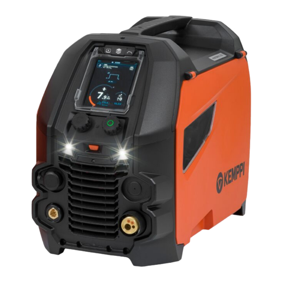
Master M 358 Operating manual - EN 1.2 Master M 358 device Front Transportation handle (also for mechanical lifting when the device is not installed on a cooling unit or cart) Control panel (and hinged control panel cover) Work lights with light switch in the middle >>... - Page 8 Master M 358 Operating manual - EN Rear Shielding gas hose connector. Mains cable Power switch Rear locking interface >> For locking on top of the cooling unit or on a cart. Inside wire feed cabinet Rotameter for gas Polarity terminals Wire inch button >>...
-
Page 9: Wire Feed Mechanism
For replacing the wire guide tubes, refer to "Installing and replacing wire guide tubes" on page 23. 1.2.2 Control panel This section describes the controls and features of the Master M 358 control panel (TFT/LCD). Left control knob (with push button function) - Page 10 Master M 358 Operating manual - EN For using the control panel, refer to "Using control panel" on page 36. © Kemppi 1921980 / 2240...
-
Page 11: Master M Cooler Cooling Unit (Optional)
Master M 358 Operating manual - EN 1.3 Master M Cooler cooling unit (optional) Front Cooler container cap Cooling liquid level indicator Cooling liquid circulation button >> Keeping the button pressed activates the pump and circulates the cooling liquid throughout the system. Once released, the pump stops. -
Page 12: Installation
Master M 358 Operating manual - EN 2. INSTALLATION Do not connect the equipment to the mains before the installation is complete. Do not modify the welding equipment in any way, except for the changes and adjustments covered in the man- ufacturer’s instructions. -
Page 13: Installing Power Source Mains Plug
Master M 358 Operating manual - EN 2.1 Installing power source mains plug Only an authorized electrician is allowed to install the mains cable and plug. Do not connect the machine to the mains before the installation is complete. Install the 3-phase plug according to the Master M device and site requirements. -
Page 14: Installing Cooling Unit (Optional)
Master M 358 Operating manual - EN 2.2 Installing cooling unit (optional) The Master M cooling unit must be installed by authorized service personnel. Tools needed: Remove the small connector cover in the rear of the power source. Route the cooling unit's connection cables so that they remain accessible through the next steps. - Page 15 Master M 358 Operating manual - EN Fix the units together with two screws (M5x12) in the front and two screws (M5x12) in the rear. Connect the cooling unit cables. Replace the small connector cover. © Kemppi 1921980 / 2240...
-
Page 16: Installing Equipment On Cart (Optional)
Master M 358 Operating manual - EN 2.3 Installing equipment on cart (optional) Master M has four transport unit options: a 4-wheel cart with a gas bottle rack (P45MT), a 4-wheel cart without a gas bottle rack (P43MT), a 2-wheel cart with a gas bottle rack (T25MT) and a 2-wheel cart without a gas bottle rack (T35A). - Page 17 Master M 358 Operating manual - EN T35A 2-wheel cart: The cart must be in horizontal position during welding. For lifting the Master M equipment, refer to "Lifting equipment" on page 69. © Kemppi 1921980 / 2240...
-
Page 18: Connecting Welding Gun
Operating manual - EN 2.4 Connecting welding gun Master M is designed to be used with the Kemppi Flexlite GX welding guns. For the Flexlite GX operating instructions, refer to userdoc.kemppi.com. Always check that the wire liner, contact tip and gas nozzle are suitable for the job. -
Page 19: Installing Earth Return Cable
Master M 358 Operating manual - EN 2.5 Installing earth return cable Connect the earth return cable to the Master M machine's earth return cable connector. © Kemppi 1921980 / 2240... -
Page 20: Installing Remote Control (Optional)
Master M 358 Operating manual - EN 2.6 Installing remote control (optional) Remote controls are optional. To enable remote operation, connect the remote control device to the Master M welding equipment. The remote control mode can be set and adjusted in the control panel settings ("Control panel: Device set- tings"... -
Page 21: Installing And Replacing Feed Rolls
Master M 358 Operating manual - EN 2.7 Installing and replacing feed rolls Replace the feed rolls when the filler wire diameter or material changes. Select the feed rolls according to the tables in "Wire feeder consumables" on page 88. Open the wire feed cabinet hatch. - Page 22 Master M 358 Operating manual - EN The pressure rolls' mounting pins have central axles attached to them, whereas the drive rolls' central axles act as drive shafts attached directly to the wire feed mechanism/motor. Remove the drive rolls and pressure rolls.
-
Page 23: Installing And Replacing Wire Guide Tubes
Master M 358 Operating manual - EN 2.8 Installing and replacing wire guide tubes The wire feed mechanism includes three wire guide tubes. Replace them when the filler wire diameter or material changes. Select the wire guide tubes according to the tables in "Wire feeder consumables" on page 88. -
Page 24: Installing And Changing Wire
Master M 358 Operating manual - EN 2.9 Installing and changing wire Always ensure that the feed rolls are suitable for the filler wire (diameter and material) in question. For more information, refer to "Wire feeder consumables" on page 88. Install the welding gun to the Master M device before installing the wire spool. - Page 25 Master M 358 Operating manual - EN If needed, adjust the spool brake by turning the spool brake tightening knob in the center of the spool hub. To install the filler wire: Release the filler wire end from the spool and cut off any deformed section so that the end is straight.
- Page 26 Master M 358 Operating manual - EN Guide the filler wire through the inlet guide tube (a) and middle guide tube (b) and into the outlet guide tube (c), which feeds the filler wire to the welding gun. Push the filler wire by hand into the gun so that the wire reaches the wire liner.
- Page 27 Master M 358 Operating manual - EN Adjust the pressure of the feed rolls with the pressure adjustment wheels. The pressure is the same for both feed roll pairs. The graduated scales on the pressure handle indicate the pressure applied to the feed rolls. Adjust the pressure of the feed rolls according to the table below.
- Page 28 Master M 358 Operating manual - EN Before welding, ensure that the welding parameters and settings conform to your welding setup. * Feed roll profiles and corresponding symbols Feed roll profile Symbol V-groove V-groove, knurled U-groove © Kemppi 1921980 / 2240...
-
Page 29: Installing Gas Bottle And Testing Gas Flow
- Do not use the whole contents of the bottle. - Always use an approved and tested regulator and flow meter. Contact your local Kemppi dealer for choosing the gas and the equipment. Without gas bottle cart: Place the gas bottle in a suitable, secure location. - Page 30 Master M 358 Operating manual - EN If not already, connect the welding gun to the device (refer to "Connecting welding gun" on page 18). Connect the gas hose to the welding device. Open the gas bottle valve. Press the gas test button (*) to test and adjust the gas flow. Use either the built-in rotameter or an external flow meter and regulator for measuring and adjustment.
-
Page 31: How To Get Welding Programs
Operating manual - EN 2.11 How to get welding programs The Master M 358 device comes with a welding program work pack preinstalled. These work pack versions cover the basic welding tasks with the automatic 1-MIG and pulsed welding process. -
Page 32: Operation
Master M 358 Operating manual - EN 3. OPERATION Before using the equipment, ensure that all the necessary installation actions have been completed according to your equipment setup and instructions. Welding is forbidden in places where there is an immediate fire or explosion hazard! The wire feed cabinet hatch must be kept closed when welding. -
Page 33: Preparing Welding System For Use
Preparing cooler Fill the coolant container inside the cooler with Kemppi cooling liquid. For instructions on filling the cooler, refer to "Filling cooler and circulating coolant" below. To weld, you must pump the coolant through the system by pressing the coolant circulation button in the front panel of the cooling unit. - Page 34 Master M 358 Operating manual - EN Open the cooler cap. Fill the cooler with coolant. Do not fill over the max. marking. Close the cooler cap. To circulate the coolant: Press the coolant circulation button in the cooler front panel (*). It activates the motor, which pumps the coolant to the hoses and to the welding gun.
-
Page 35: Calibrating Welding Cable
Master M 358 Operating manual - EN 3.2 Calibrating welding cable The welding cable resistance can be measured using the built-in cable calibration function without an additional meas- urement cable. This calibration function is available only in MIG operation mode. -
Page 36: Using Control Panel
Operating manual - EN 3.3 Using control panel The Master M 358 control panel includes advanced features and functions for MIG welding with the option to use Master M 358 also for TIG (DC) and MMA welding. The automatic 1-MIG process is available along with the Kemppi welding programs as well as Wise features and MAX processes (optional). -
Page 37: Control Panel: Home View
(Weld data) is displayed briefly. 3.3.1 Control panel: Home view Master M 358 control panel's Home view is also the main welding view. Memory channel information Applied welding parameters and functions Wire feed speed (MIG) or welding current (TIG, MMA) Active welding process Applied device settings (e.g. -
Page 38: Control Panel: Weld Assist
Master M 358 Operating manual - EN • Pulse MIG: Wire feed speed adjustment • DPulse MIG: Wire feed speed adjustment and switching between pulse levels with control knob button • TIG/MMA: Welding current adjustment Right control knob: • Manual MIG: Welding voltage adjustment •... -
Page 39: Control Panel: Channels
Master M 358 Operating manual - EN Weld Assist gives you a recommendation for these welding parameters: >> Welding process >> Wire feed speed >> Gas flow rate >> Travel speed >> Separate values for root and fill passes (where applicable). - Page 40 Master M 358 Operating manual - EN The amount of available memory channels differs between different operation modes: MIG (100 channels), TIG (10 chan- nels) and MMA (10 channels). The operation mode set in the control panel Settings determines for which main welding process the memory chan- nels are shown.
-
Page 41: Control Panel: Wps View
Complete the registration process as instructed on the registration page. You will be required to fill in the serial number and four-digit security pin of your Master M 358 machine. These can be found on the machine rating plate. - Page 42 Master M 358 Operating manual - EN Select the desired dWPS for viewing and for selecting a weld pass by turning the right control knob and pressing the right control knob button. If a dWPS and weld pass have already before been linked to the active memory channel, the WPS view opens directly to that WPS.
- Page 43 Master M 358 Operating manual - EN If a memory channel has been already linked to the weld pass, you can activate the selected weld pass and the default memory channel by selecting 'Activate'. If a memory channel has not been linked to the weld pass previously, you can link the weld pass to an existing memory channel ('Select linked channel').
-
Page 44: Control Panel: Welding Parameters
Master M 358 Operating manual - EN 3.3.5 Control panel: Welding parameters The Welding parameters view includes a start and stop curve for adjusting the most essential parameters for a weld. The bottom section of the view lists the available adjustments for the selected welding process. The welding process selec- tion is based on the active memory channel and its settings. - Page 45 Master M 358 Operating manual - EN Welding parameters and feature descriptions MIG and 1-MIG welding parameters The parameters listed here are available for adjustment with the MIG and 1-MIG processes. Parameter Parameter value Description Process MIG, 1-MIG, Pulse, DPulse, MAX Cool,...
- Page 46 Master M 358 Operating manual - EN Dynamics -10.0 ... +10.0, step 0.2 Controls the short circuit behavior of Default = 0 the arc. The lower the value the softer the arc, the higher the value the rougher the arc.
- Page 47 Master M 358 Operating manual - EN 1-MIG welding parameters The parameters listed here are available for adjustment only with the 1-MIG process. Parameter Parameter value Description Trigger logic 2T, 4T, Powerlog (2 levels or 3 levels) Welding guns can have several altern- ative trigger operation modes (trigger logics).
- Page 48 Master M 358 Operating manual - EN Pulse/DPulse welding parameters The parameters listed here are available for adjustment in addition to the MIG and 1-MIG welding parameters. Parameter Parameter value Description Pulse current % -10 ... +15 %, step 1...
- Page 49 Master M 358 Operating manual - EN MAX Position parameters The parameters listed here are MAX Position process specific. Parameter Parameter value Description MAX Position frequency -0.5 ... +0.5 Hz, step 0.1 MAX Position frequency fine tuning. Default = 0 Pulse current % -10 …...
-
Page 50: Control Panel: Weld History
Master M 358 Operating manual - EN 3.3.6 Control panel: Weld history The Weld history view collects the information of the past welds (the last 10) into one view for later checking. To change how the weld data averages are calculated (with or without slope phases) refer to "Control panel: Device settings" on the next page. -
Page 51: Control Panel: Device Settings
Master M 358 Operating manual - EN 3.3.8 Control panel: Device settings Changing settings Turn the right control knob to highlight the desired settings parameter. Press the right control knob to select the settings parameter for adjustment. Turn the right control knob to select the settings value. - Page 52 Master M 358 Operating manual - EN Remote control OFF/Remote/Gun If remote controller is not connected, this Default = OFF selection is not available. Remote mode Wire feed speed / Channel This determines what is changed with (with 1-knob remote control) the remote, wire feed speed or memory channel (available channels: 1...5).
-
Page 53: Control Panel: Applying Welding Programs
The screensaver image is shown on dis- Screensaver Default = 5 min play after the set time period. By default, the Kemppi logo is shown. To change the screensaver image, refer to "USB update" on page 64. Start/Cancel The date and time and the calibration... - Page 54 Master M 358 Operating manual - EN Go to the Memory channels view. (Refer to "Control panel: Channels" on page 39 for more information.) Enter the actions menu. Select Create channel. >> A filter view opens. Use the filter options (e.g. material, wire material or wire diameter) to find the welding programs best suited for the purpose.
-
Page 55: Control Panel: Weld Data View
Master M 358 Operating manual - EN To save, scroll down to Save to and select it. Select the memory channel slot for saving and confirm. Once ready, you can continue to the Welding parameters view to adjust the welding settings for the new channel, create a new channel or go back to the Channels view. -
Page 56: Additional Guidance To Functions And Features
Master M 358 Operating manual - EN 3.4 Additional guidance to functions and features This section summarizes the Master M 358 functions and features and how to use them. 3.4.1 Trigger logic functions You can select the trigger logic in the Welding parameters view. -
Page 57: 1-Mig
>> To fine tune the heat output while welding, in the control panel's Home view, turn the right control knob. For more information on Wise products, visit www.kemppi.com. 3.4.4 WisePenetration+ feature In standard MIG/MAG welding, changes in stick-out length cause welding current to fluctuate. WisePenetration+ main- tains constant welding current by controlling the wire feed speed according to the stick-out length. -
Page 58: Wisesteel Feature
>> To fine tune the heat output while welding, in the control panel's Home view, turn the right control knob. For more information on Wise products, visit www.kemppi.com. 3.4.5 WiseSteel feature The WiseSteel welding feature is based on modifying the conventional MIG/MAG arcs to enable higher quality of welds. -
Page 59: Pulse Welding
Master M 358 Operating manual - EN 3.5 Pulse welding The advantages of Pulse are a higher welding speed and deposition rate compared to short-arc welding, lower heat input compared to spray-arc welding, a spatter-free globular arc and smooth appearance of the weld. Pulse is suitable for all position welding. -
Page 60: Max Position Process
Master M 358 Operating manual - EN • CuSi3 & Ar (1.0 mm) • CuAl8 & Ar (1.0 mm). 3.5.2 MAX Position process MAX Position is a synergic MIG/MAG welding process optimized for vertical fillet welds (position: PF). MAX Position auto- matically switches between two separate power levels. -
Page 61: Wireless Connection (Wlan)
Master M 358 Operating manual - EN 3.6 Wireless connection (WLAN) To connect the welding equipment to your local wireless network: On the control panel, go to the WLAN view. Turn the WLAN feature on by turning and pressing the right control knob. -
Page 62: Digital Welding Procedure Specification (Dwps)
Digital Welding Procedure Specification (dWPS) is a WPS in digital format that can be set to observe the welding para- meters of the Master M 358 equipment. The WPSes can be read on the control panel display and/or a memory channel can be linked with a WPS. -
Page 63: Weldeye With Dcm
Complete the registration process as instructed on the registration page. Once finished, the equipment is con- nected to WeldEye ArcVision. You will be required to fill in the serial number and four-digit security pin of your Master M 358 machine. These can be found on the machine's rating plate. -
Page 64: Usb Backup And Restore
If restoring from a backup, go to the device settings and select Restore. Open the USB connector cover and connect the USB memory stick to the Master M 358 control panel. Follow the steps on the control panel screen to complete the backup/restore operation. - Page 65 Following the on-screen instructions, upload, edit and download the new screen saver image onto a USB memory stick. Connect the USB memory stick to the Master M 358 control panel following the same principle as with the software updates (previous chapter) and the on-screen instructions.
-
Page 66: Using Remote Control
Master M 358 Operating manual - EN 3.7 Using remote control Remote control HR43 To adjust the wire feed speed, turn the knob on the remote control. To change the memory channel instead of the wire feed speed with the remote, change the remote mode setting in the "Control panel: Device settings"... -
Page 67: Changing Welding Polarity
Master M 358 Operating manual - EN 3.8 Changing welding polarity Welding polarity needs to changed for TIG welding. Also, some filler wires require changing the welding polarity. Check the recommended welding polarity on the filler wire package. Before handling electrical parts, ensure the welding device is disconnected from the mains. - Page 68 Master M 358 Operating manual - EN Connect the cables to the polarity terminals according to the polarity recommendation. Replace the washers and bolts. Tighten to 17 Nm torque. Replace the protective rubber covers. © Kemppi 1921980 / 2240...
-
Page 69: Lifting Equipment
Master M 358 Operating manual - EN 3.9 Lifting equipment If a gas bottle is installed on cart, DO NOT attempt to lift the cart with the gas bottle in place. 4-wheel cart: Ensure that the welding equipment is properly secured to the cart. -
Page 70: Maintenance
Master M 358 Operating manual - EN 4. MAINTENANCE When considering and planning routine maintenance, consider the operating frequency of the welding system and the working environment. Correct operating of the welding machine and regular maintenance helps you avoid unnecessary downtime and equip- ment failure. -
Page 71: Daily Maintenance
Check the wire feed rolls and the pressure handle. Clean and lubricate with a small quantity of light machine oil if needed. For repairs, contact Kemppi at www.kemppi.com or your dealer. Welding gun maintenance For Flexlite GX MIG gun instructions, refer to userdoc.kemppi.com. © Kemppi 1921980 / 2240... -
Page 72: Periodic Maintenance
Master M 358 Operating manual - EN 4.2 Periodic maintenance Only qualified service personnel is allowed to carry out periodic maintenance. Only an authorized electrician is allowed to carry out electrical work. Before removing the cover plate, disconnect the power source from the mains and wait for about 2 minutes before discharging the capacitor. -
Page 73: Service Workshops
Master M 358 Operating manual - EN 4.3 Service workshops Kemppi Service Workshops complete the welding system maintenance according to the Kemppi service agreement. The main aspects in the service workshop maintenance procedure are: • Cleanup of the machine •... -
Page 74: Troubleshooting
Master M 358 Operating manual - EN 4.4 Troubleshooting The problems listed and the possible causes are not definitive, but suggest some typical situations that may turn up during normal use of the welding system. Welding device: Problem Recommended actions The welding device does not power up Check that the mains cable is plugged in properly. - Page 75 Master M 358 Operating manual - EN Dirty and/or poor quality weld Check that the shielding gas has not run out. Check that the shielding gas flow is unobstructed. Check that the gas type is correct for the application. Check the polarity of the gun/electrode.
-
Page 76: Error Codes
Too long welding session with high power. Do not shut down, let the fans cool the machine. If overheated fans are not running, contact Kemppi service Internal 24V Power source contains an inoperative 24V Restart the power source. If problem persists, contact voltage is too power supply unit . - Page 77 Master M 358 Operating manual - EN VRD error Open circuit voltage exceeds the VRD limit. Restart the power source. If problem persists, contact Kemppi service. High current in There may be too much pressure in the Adjust the feed roll pressure. Clean the wire line.
-
Page 78: Installing And Cleaning Power Source Air Filter (Optional)
Master M 358 Operating manual - EN 4.6 Installing and cleaning power source air filter (optional) An optional power source air filter can be purchased separately. The air filter comes with a fixed casing designed to be mounted directly onto the power source air intake. - Page 79 Master M 358 Operating manual - EN Cleansing Remove the air filter from the power source by releasing the clips on the edge of the air filter casing. Blow the air filter clean with compressed air. © Kemppi 1921980 / 2240...
-
Page 80: Disposal
The owner of the equip- ment is obliged to deliver a decommissioned unit to a regional collection center, as per the instructions of local author- ities or a Kemppi representative. By applying these European Directives you improve the environment and human health. -
Page 81: Technical Data
5. TECHNICAL DATA Technical data: • For Master M 358 device technical data, refer to "Master M 358 device" on the next page. • For Master M Cooler cooling unit technical data, refer to "Master M cooling unit" on page 86. -
Page 82: Master M 358 Device
Master M 358 Operating manual - EN 5.1 Master M 358 device Master M 358 G Master M 358 358 G Feature Value Mains connection voltage 3~50 Hz 380...460 V ±10 % Mains connection cable HO7RN-F 4 mm² Input power at rated maximum cur-... - Page 83 2.412...2.484 GHz, 5.150...5.850 SAMSUNG SDI: INR18650-26J; Lithium-ion battery 3,6 V; 2600 mAh LG CHEM: ICR18650HE4; 3,6 V; 2500 mAh IEC 60974-1, -10 Standards Master M 358 GM Master M 358 358 GM Feature Value 220...230 V ±10 % Mains connection voltage 3~50 Hz 380...460 V ±10 %...
- Page 84 Master M 358 Operating manual - EN No-load state power consumption MMA (power save) @ 400 V 20 W MMA (fans ON) @ 400 V 120 W No-load voltage @ 220...230 V 54 ... 56 V @ 380...460 V 55 ... 69 V Open circuit voltage 53 ...
- Page 85 Master M 358 Operating manual - EN Degree of protection IP23S External dimensions L x W x H 602 x 298 x 447 mm Package external dimensions L x W x H 610 x 300 x 445 mm, with cooler 700 mm...
-
Page 86: Master M Cooling Unit
Master M 358 Operating manual - EN 5.2 Master M cooling unit Master M Cooler Master M Cooler Feature Value Supply voltage 380...460 V +/- 10 % Maximum supply current @ 380...460 V 0.7 A 1max Cooling power @ 1 l/min 1.0 kW... -
Page 87: Master M 358 Ordering Info
Master M 358 Operating manual - EN 5.3 Master M 358 ordering info For Master M 358 ordering information and optional accessories, refer to Kemppi.com. © Kemppi 1921980 / 2240... -
Page 88: Wire Feeder Consumables
The wire feeder consumables can be ordered in Configurator.kemppi.com. In the tables, standard refers to plastic feed rolls and heavy-duty refers to metal feed rolls. The materials mentioned first refer to primary suitability and the materials mentioned inside brackets refer to secondary suitability. - Page 89 Master M 358 Operating manual - EN Feed rolls The table below lists the standard feed rolls available. Feed rolls, standard Filler wire diameter Filler wire material Feed roll profile* Drive roll code Pressure roll code (mm) Fe, Ss, Cu (Al, MC/FC)
-
Page 90: Welding Program Work Packs
Welding program work packs include a set of standard welding programs to allow welding with e.g. automatic 1-MIG and pulse processes. For more information on the available Master M welding program options and installing the weld- ing programs or software updates, contact your local Kemppi dealer or go to Kemppi.com. 1-MIG work pack:... - Page 91 Master M 358 Operating manual - EN Pulse work pack: The Pulse work pack includes also all 1-MIG work pack welding programs. Welding program Process Wire material Wire diameter Shielding gas Description Pulse AlMg5 Standard Pulse AlMg5 Standard Pulse AlSi5...
Need help?
Do you have a question about the Master M 358 and is the answer not in the manual?
Questions and answers