
Related Manuals for Pfeiffer Vacuum Compact Turbo TMH 262 N


Summary of Contents for Pfeiffer Vacuum Compact Turbo TMH 262 N
- Page 1 Betriebsanleitung • Operating Instructions Translation of the Original Operating Instructions Compact Turbo™ TurboDrag Pump TMH 262 N TMU 262 N...
-
Page 2: Table Of Contents
Connections to the turbopump ......12 Connecting Pfeiffer Vacuum display and control units or PC ..15 Connecting the remote control . -
Page 3: About This Manual
1 About this manual 1.1 Validity This operating manual is for customers of Pfeiffer Vacuum. It describes the func- tioning of the designated product and provides the most important information for safe use of the unit. The description follows applicable EU guidelines. All informa- tion provided in this operating manual refer to the current state of the product's de- velopment. - Page 4 About this manual Piktograph Prohibition of an action or activity in connection with a definitions source of danger, the disregarding of which may result in serious accidents. Warning of a displayed source of danger in connection with operation of the unit or equipment. Command to perform an action or task associated with a source of danger, the disregarding of which may result in serious accidents.
-
Page 5: Safety
NOTE Installation and operation of accessories Pfeiffer Vacuum pumps can be equipped with a series of adapted accessories. The installation, operation and maintenance of connected devices are described in detail in the operating instructions of the individual components. -
Page 6: Transport And Storage
• Installation in systems where the turbopumps are subjected to impact-like stress and vibrations or the effect of periodically occurring forces. • The use of accessories, which are not named in this manual or not authorised by Pfeiffer Vacuum 3 Transport and storage 3.1 Transport Reuse the transport container. -
Page 7: Product Description
D = "Drag" pump for the medium N = Integrated power supply vacuum range To correctly identify the product when communicating with Pfeiffer Vacuum, al- ways have the information from the rating plate available. D-35614 Asslar PM 063 265 -T... -
Page 8: Range Of Application
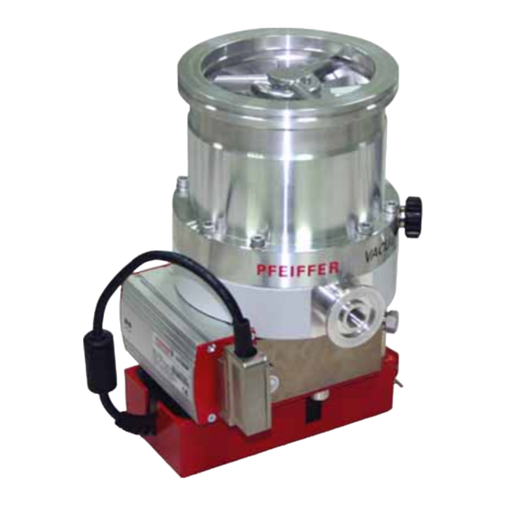
Product description Sealing gas connection High vacuum flange Electronic drive unit TC 100 Integrated power supply Venting screw 20a Fore-vacuum flange Mains connection X1 Connecting plug X3 Fig. 2: View of CompactTurbo™ TMH 262 N Cooling • Air cooling In the case of excess temperature the electronic drive unit reduces the rotor rota- tion speed automatically. -
Page 9: Installation
Consult Pfeiffer Vacuum for special requirements. NOTE Installation and operation of accessories Pfeiffer Vacuum pumps can be equipped with a series of adapted accessories. The installation, operation and maintenance of connected devices are described in detail in the operating instructions of the individual components. - Page 10 • The operating fluid reservoir is already installed and filled for the turbopumps TMH/U 262 N. Use of a splinter The installation of a Pfeiffer Vacuum centering ring with splinter shield or protec- tion screen in the high vacuum flange protects the turbopump against foreign bod- shield or protection ies coming from the recipient.
- Page 11 The com- ponents for installing the turbo pumps are special designs of Pfeiffer Vacuum. Ob- serve the minimum strength of 170 N/mm for the flange material.
-
Page 12: Connections To The Turbopump
5.4 Connections to the turbopump The connection of Pfeiffer Vacuum display and control units and two optional ac- cessory components is possible by using the connection box TCS 010. - Page 13 Attach and fix the TCS 010 to the electronic drive unit. Connecting the fore- Recommendation: As backing pump, use a dry-compressing diaphragm pump or rotary vane pumps from the Pfeiffer Vacuum programme. The backing pump must vacuum side generate a vacuum pressure of ≤ 5 mbar.
- Page 14 Installation Pump lower part Sealing gas connection Locking screw O-ring Sealing gas valve O-ring 3b 3c Fig. 5: Connecting the sealing gas valve Unscrew the screw plug with sealing ring out of the sealing gas connection of the turbopump. Screw the sealing gas valve with seal ring into the purge gas connection. Obtain details on adjusting the sealing gas quantity from the corresponding operating manual.
-
Page 15: Connecting Pfeiffer Vacuum Display And Control Units Or Pc
Installation 5.5 Connecting Pfeiffer Vacuum display and control units or PC USB/RS485-converter RS-232 TIC 001 RS-485 TC 100 TC 100 HPU 001 TC 100 + TCS 010 Fig. 6: Connecting the serial interface RS485 An external operating part (DCU or HPU 001) or an external computer can be con- nected via the connection with the designation "RS485"... -
Page 16: Connecting The Remote Control
Installation CAUTION Danger of electric shock The insulation measures of the bus system are designed only for use with safety extra- low voltage. Connect only suitable devices to the bus system. The connections must be made in accordance with the specification of the inter- face RS485. - Page 17 Installation Pin assignment and Reference voltage function of the plug Pin Function +24 V ± 5 % Supply voltage (I = 4,2 A; I = 4,6 A) cont Ground Ground potential for all inputs and outputs Inputs Pin Function Open (low) Closed (high) Remote: Priority of interface Local: Priority of inputs (Pin 3 -...
-
Page 18: Connections Diagram Tc
Installation 5.7 Connections diagram TC External connection TC 100 Remote/Local Remote/Local Accessory 1 Accessory 1 Accessory 2 venting valve Accessory 2 cooling unit Pumping station relay Pumping station Standby/Reset Standby/Reset 24 VDC* 24 VDC* venting valve cooling unit relay Accessory output 1 24 VDC/max. -
Page 19: Operation
6 Operation NOTE Installation and operation of accessories Pfeiffer Vacuum pumps can be equipped with a series of adapted accessories. The installation, operation and maintenance of connected devices are described in detail in the operating instructions of the individual components. - Page 20 Operation Observe the following documents for operation with Pfeiffer Vacuum display and control units: • Operating instructions DCU • Operating instructions HPU 001 • Pumping operations with DCU Operation with re- Remote control options are provided via the 15-pole D-Sub connector with the des- ignation ”X3“...
-
Page 21: Monitoring Of The Operation Conditions
Pumping of gases with the molecular mass ≥ 40 in the wrong gas mode can lead to destruction of the pump. Ensure the gas mode is correctly set. Contact Pfeiffer Vacuum before using gases with a greater molecular mass. Hochlauf D-C = Gas mode «0»... -
Page 22: Switching Off And Venting
– The valve cross section for the venting rate of 15 mbar/s must be adapted to the size of the vacuum chamber. – For small vacuum chambers, use the Pfeiffer Vacuum TVF 005 venting valve. Then vent with an additional venting valve of any desired size. -
Page 23: Maintenance / Replacement
Decontaminate affected parts before carrying out maintenance work. NOTE Disclaimer of liability Pfeiffer Vacuum accepts no liability for personal injury or material damage, losses or operating malfunctions due to improperly performed maintenance. The liability and warranty entitlement expires. 7.1 Maintenance intervals and responsibilities •... -
Page 24: Replacing The Integrated Power Supply
Maintenance / replacement 7.2 Replacing the integrated power supply Turn off the vacuum pump, vent to atmospheric pressure and allow to cool, if necessary. Remove the mains plug from the power supply. Remove the vacuum pump from the system, if necessary. Close the flange openings by using the original protective covers. -
Page 25: Replacing The Operating Fluid Reservoir
Maintenance / replacement 7.3 Replacing the operating fluid reservoir WARNING Poisoning hazard through contact with materials that damage health. The operating fluid reservoir and parts of the pump may contain toxic substances from the pumped media. Dispose of operating fluid reservoir in accordance with the applicable regulations. Safety data sheet on request or under www.pfeiffer-vacuum.net Prevent health hazards or environmental damage due to contamination by means of appropriate safety precautions. - Page 26 Maintenance / replacement Standard version Turn off the vacuum pump, vent to atmospheric pressure and allow to cool, if necessary. Remove the vacuum pump from the system, if necessary. Close the flange openings by using the original protective covers. Turn the turbopump over onto the closed high vacuum flange. Screw out the end cover on the bottom of the turbopump with special tool E.
- Page 27 Felt washer in the lubricant reservoir packet The felt washer in the operating fluid reservoir is necessary only for special service work and is replaced by Pfeiffer Vacuum Service. Remove impurities from the turbopump and the end cover with a clean, lint-free cloth.
-
Page 28: Replacing The Electronic Drive Unit
Maintenance / replacement 7.4 Replacing the electronic drive unit WARNING Danger of electric shock Even after mains power is switched off, the subsequently running turbopump delivers voltages > 50 V . There is a danger of electric shock when touching open contacts eff. -
Page 29: Decommissioning
Check turbopump for contamination and moisture. Clean the turbopump externally with a lint-free cloth and little industrial alcohol. If necessary, have Pfeiffer Vacuum Service clean the turbopump completely. If necessary, have the bearings replaced. Take into account the total running time. -
Page 30: Malfunctions
Red LED on the TC 100 is flashing Check partial mains voltage – Power failure Check partial mains voltage for earthing Check mains power supply to the power ad- apter If no Pfeiffer Vacuum control panel is available, please contact Pfeiffer Vacuum Service... -
Page 31: Service
Service 10 Service Pfeiffer Vacuum offers first-class service! • Operating fluid and bearing change on the spot by Pfeiffer Vacuum FieldService • Maintenance / repair in the nearby ServiceCenter or ServicePoint • Fast replacement with exchange products in mint condition •... -
Page 32: Spare Parts Tmh/U 262 N
Spare parts TMH/U 262 N 11 Spare parts TMH/U 262 N Item Designation Size Order Number Notes Pieces Order Qty End cover M40 x 1 PM 003 619 Lubricant reservoir PM 063 265 -T incl. O-ring incl. 8 x Porex rod (7a), O- Lubricant reservoir ("Y") PM 053 266 -T ring, felt washer... -
Page 33: Accessories
PF 144 020 Vibration compensator DN 100 ISO-K PM 006 459 -X Vibration compensator DN 100 CF-F PM 006 488 -X Pfeiffer Vacuum protocol RS232/RS485 PM 0488 BN interface protocol TIC 001 Interface converter RS232 in RS485 PM 051 054 -T... -
Page 34: Technical Data
Technical data 13 Technical data Parameter TMH 262 P N TMU 262 P N Flange (in) DN 100 ISO-K DN 100 CF-F Flange (out) DN 25 ISO-KF / G 1/4" 25 ISO-KF / G 1/4" Venting connection G 1/8" G 1/8'' Rotational speed ±2% 60000 rpm 60000 rpm... -
Page 35: Dimension Diagrams
Technical data 13.1 Dimension diagrams DN 25 ISO-KF / G1/4" DN 25 ISO-KF / G1/4" 94.5 94.5 DN 100 ISO-K DN 100 CF-F Ø 138.5 Ø 138.5 Fig. 9: TMH 262 PN / TMH 262 YPN Fig. 10: TMU 262 PN / TMU 262 YPN... -
Page 36: Manufacturer's Declaration
In addition, the product cited below satisfies all relevant provisions of EC direc- tive "Electromagnetic Compatibility" 2004/108/EC . The agent responsible for compiling the technical documentation is Mr. Jörg Stanzel, Pfeiffer Vacuum GmbH, Berliner Straße 43, 35614 Aßlar. TMH/U 262 N Guidelines, harmonised standards and national standards and specifications... - Page 37 Roots pumps Dry compressing pumps Leak detectors Valves Components and feedthroughs Vacuum measurement Gas analysis System engineering Service Pfeiffer Vacuum Technology AG · Headquarters/Germany Tel. +49-(0) 64 41-8 02-0 · Fax +49-(0) 64 41-8 02-2 02 · info@pfeiffer-vacuum.de · www.pfeiffer-vacuum.net...
Need help?
Do you have a question about the Compact Turbo TMH 262 N and is the answer not in the manual?
Questions and answers