
Related Manuals for Pfeiffer Vacuum TSH 071


Summary of Contents for Pfeiffer Vacuum TSH 071
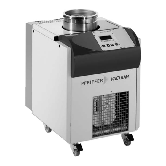
- Page 1 Betriebsanleitung • Operating Instructions Turbomolecular Drag Pumping Stations TSH 071 / TSU 071 TSH 261 / TSU 261 TSH 521 / TSU 521...
-
Page 2: Table Of Contents
Index Page Page 1. Safety Instructions ........3 5. What To Do In Case 1.1. For Your Orientation............3 Of Breakedowns? ........11 1.2. Pictogram Definitions............3 6. Maintenance .......... 12 2. Understanding The 6.1. Replacing The Lubricant Reservoir And Pumping Stations ........ -
Page 3: Safety Instructions
1. Safety Instructions ☞ Read and follow all instructions in this manual. 1.1. For Your Orientation – Inform yourself regarding: – Hazards which can be caused by the pumping station; Instructions in the text – Hazards which can be caused by your system; ➡... -
Page 4: Understanding The Pumping Stations
Pumping Station Control Operating Instructions Alternative: Water cooling (please see Section 9. for DCU/TPS Accessories). TSH 071 TC 600 with TSU 071 DCU 001 and TPS 100 Details regarding the pumping station PLEASE NOTE components can be found in the respective... -
Page 5: Pumping Station Components
– Diaphragm pumps do not require lubricant. The venting mode of the TVF 005 is selected via the DCU. – Permissible magnetic fields: ≤ Drying Unit TTV 001 (Accessory) TSH 071/TSU 071 4 mT ≤ TSH 261/TSU 261 5.5 mT The drying unit keeps moisture away from the apparatus ≤... -
Page 6: Electrical Connections
3.4. Electrical Connections Piping must be connected free of stress. CAUTION A bellows fitted in the piping will compensate The electrical connections must be effected in for any stress arising. CAUTION accordance with local regulations. The voltage requirements shown on the rating plate must comply with the mains voltage. -
Page 7: Pumping Station Connections Plan General Schema
3.7. Pumping Station Connections Plan General Schema... -
Page 8: Connection Involving Rotary Vane Vacuum Pumps
Connection Involving Rotary Vane Vacuum Pumps... -
Page 9: Connection Involving Diaphragm Pumps
Connection Involving Diaphragm Pumps... -
Page 10: Operations
4. Operations 4.1. Transportation Protection 4.2. Filling In The Lubricant Pumping stations which contain a Diaphragm Pump – The t t u u r r b b o o m m o o l l e e c c u u l l a a r r d d r r a a g g p p u u m m p p bearing has been filled MVP 055-3 or a rotary vane vacuum pump are shipped with with the required amount of lubricant in the works. -
Page 11: Starting
4.4. Starting – Once the self test has been successfully completed (duration: TSH/TSU 071 approximately 10 s; TSH/TSU 261 Turbopump rotors turn at great speed. When the approximately 10 s; TSH/TSU 521 approximately 15 s), WARNING high vacuum flange is open there is a danger of the pumping station begins to operate. -
Page 12: Maintenance
6. Maintenance ➡ Screw back in operating fluid drain screw 7 taking care Maintenance on the individual components of PLEASE NOTE with the O-ring. the pumping station should be carried out in ➡ Fill in operating fluid as described in Section 4.1. of these accordance with the instructions in the operating instructions. -
Page 13: Service
➡ A copy of the completed declaration must accompany the unit; any additional copies must be sent to your local Pfeif- fer Vacuum Service Center. Please get in touch with your local Pfeiffer Vacuum represen- tatives if there are any questions regarding contamination. -
Page 14: Technical Data
8. Technical Data 1) Final pressure only reachable with metal sealing of the high vacuum flange... -
Page 15: Dimensions
8.1. Dimensions Schalter EIN/AUS Switch ON/OFF Netzanschluß/ Mains connection Durchführung Meßkabel/ Feedthrough Measurement cable Auspuff G1/2” 12.5 Exhaust G1/2”; G1/4” innen/inside Sperrgas/Flutgas; Sealing gas/ Venting gas; G1/8” innen/inside Wasserkühlung/ Water cooling G1/4” innen/inside Nur mit Betriebsmittel- DUO 10 / 5 ablaßrinne/ Operating fluid With DUO 10/5... -
Page 16: Accessories
9. Accessories Description Size Number Comments/ Ordering quantity relevant operating instructions Drying Unit TTV 001 PM Z00 121 filled with zeolite/ PM 0022 BN approx. 260 cm 3 Zeolite filling for the drying unit PM006 786 -T Set of rollers consist of: for mobile pumping station 2 wheels without brakes P 0994 830... -
Page 17: Declaration Of Contamination
Declaration of Contamination of Vacuum Equipment and Components The repair and/or service of vacuum components will only be The manufacturer could refuse to accept any equipment carried out if a correctly completed declaration has been without a declaration. submitted. Non-completion will result in delay. This declaration can only be completed and signed by authorised and qualified staff: 1. -
Page 18: Declaration Of Conformity
EN 292-1 EN 50 081-1 EN 292-2 EN 50 082-2 EN 294 IEC 801 1-4 EN 61 010 VDE 0843-6 EN 55 011 Unterschrift/Signature: Pfeiffer Vacuum GmbH Berliner Str. 43 Unterschriften: 35614 Asslar Germany (W. Dondorf) Geschäftsführer Managing Director Konf.I/2003... - Page 19 Latvia, Lithuania, Maldavia, Philippines, P.R. China, France Fax: +48 / 61 8677 111, Email: softrade@softrade.com.pl Rumania, Russia, Tajikistan, Turkmenistan, Ukraine, Uzbeki- Pfeiffer Vacuum France SAS 45, rue Senouque, BP 139 stan, Vietnam Portugal F-78531 BUC Cedex, Phone: +33 / (0)1 30 83 04 00, Fax: +33 / (0)1 30 83 04 04, Email: info@pfeiffer-vacuum.fr...
Need help?
Do you have a question about the TSH 071 and is the answer not in the manual?
Questions and answers