
Related Manuals for Pfeiffer Vacuum TMH 071 P


Summary of Contents for Pfeiffer Vacuum TMH 071 P
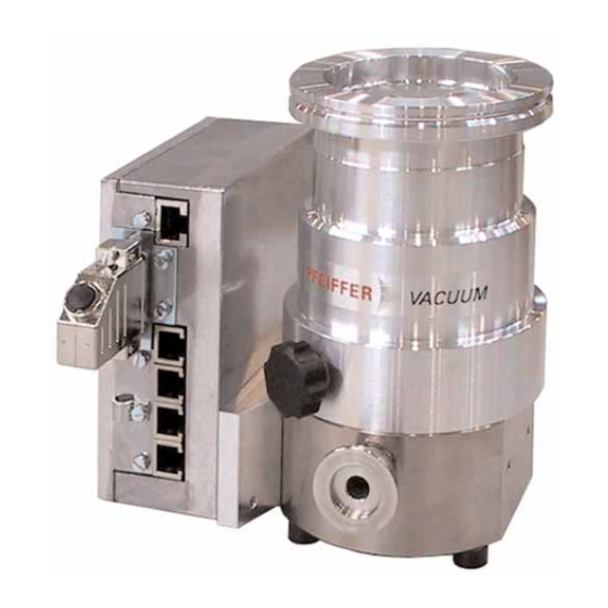
- Page 1 Betriebsanleitung • Operating Instructions Turbomolecular Drag Pumps With Electronic Drive Unit TC 600 TMH 071 P TMU 071 P...
-
Page 2: Table Of Contents
1.2. Pictogram Definitions............3 5.2. Turbopump Temperature Management....... 16 2. Understanding The Pumps 6. What To Do In Case Of TMH 071 P/TMU 071 P ......4 Breakdowns ? ........17 2.1. Main Features..............4 Maintenance.......... 18 Proper Use ................ 4 7.1. -
Page 3: Safety Instructions
1. Safety Instructions 1.1. For Your Orientation ☞ Read and follow all instructions in this manual. ☞ Inform yourself regarding: Instruction in the text – Hazards which can be caused by the pump; ➡ Working instruction: here, you have to do something. –... -
Page 4: Understanding The Pumps Tmh 071 P/Tmu 071 P
– If the process produces dust, the maintenance intervals must be specified accordingly and sealing gas must be Turbopumps TMH 071 P/TMU 071 P with the TC 600 form a used. complete unit. Voltage is supplied by the power unit (see –... -
Page 5: Installation
Connecting via a bellows – On Turbopumps TMH 071 P/TMU 071 P the lubricant reser- If the high vacuum side is to be flanged via a bellows, the tur- voir is already fitted and filled. -
Page 6: Fitting The Splinter Shield
Directly flanging the pump Fitting The Splinter Shield The turbopump can be flanged onto the vacuum chamber Insert the splinter shield in the high vacuum flange in such a vertically (0°) up to an angle of 90° maximum. way that the corrugation of the strainer points outwards. The fore-vacuum flange must always point DN 63 CAUTION... -
Page 7: Connecting The Cooling Unit
3.4. Connecting The Cooling Unit 3.6. Connecting The Casing Heating Unit Turbopumps TMH 071 P/TMU 071 P can optionally be The attainment of final pressures is accelerated when turbo- provided with enhanced convection cooling, air cooling or pumps and vacuum chambers are baked out. -
Page 8: Connecting The Electronic Drive Unit Tc 600
TC 600 performs a self test on the supply voltage. The supply voltage for Turbomolecular Pumps TMH 071 P/TMU 071 P is 24 VDC ±5% in accordance with EN 60 742. If the turbopump is being operated with the Operations And Display Unit DCU 001/100, remote plug 8d should be disconnected. -
Page 9: Connecting The Remote Control Unit
3.10. Connecting The Remote Control Unit Remote control options for various functions are provided with Pin occupancy remote plug the connection "REMOTE" on the TC 600 via the 15-pole D-Sub- Connector. Shielded cable must be used. Shielding is on the plug side of the TC 600 connected to the TC casing. -
Page 10: Connecting The Serial Interface Rs 485
3.11. Connecting The Serial Interface RS 485 Connecting The RS 485 An external operating component (DCU 001/DCU 100) or an Connection to a fixed bus system external computer can be connected via the connection ➡ Connect all units with D+ (pin 5 / RS 485) and D- (pin 7 / ”RS 485”... -
Page 11: Connections Diagram
3.12. Connections Diagram TC 600 TC 750 n.c. +24 VDC*/max. 200 mA (supply voltage, DCU) n.c. n.c. RS 485 RS 485+/ (DO/RI) GND* (mass connection, DCU) RS 485- / (DO/RI) n.c. +24 VDC*/max. 50 mA Venting release Motor, turbopump Contact current max. Pumping station 6 mA / Contact Heating/Reset... -
Page 12: Operations
4. Operations 4.1. Before Switching On 4.2. Switching ON ➡ Switch on the turbopump with switch S1 on the power Sections 4.1. to 4.3. refer only to operating the pump in its condition on delivery, without the DCU operating unit. The unit. -
Page 13: Switching Off And Venting
Where small vacuum chambers are involved, the For the vertex of the power characteristic line please refer to Pfeiffer Vacuum Venting Valve TVF 005 can be used for first Section 9. Technical Data. stage venting. -
Page 14: Shutting Down For Longer Periods
(please contact for 3600 s long as sufficient Pfeiffer Vacuum Service). (works setting) energy is generated by the turbopump 1) When mains power is restored the venting procedure is interrupted. -
Page 15: Pumping Station
Pumping Station Switching Outputs Any connected pumping station components are started up Switching outputs 1 and 2 can be loaded with a maximum (e.g. backing pump, venting valve, air cooling) and with simul- 24 V / 50 mA per output. The following functions are assigned taneous activation of the input ”motor, turbopump”... -
Page 16: Monitoring Operations
5. Monitoring Operations 5.1. Operations Display Via LED 5.2. Turbopump Temperature Management Certain operations modes of the turbopump and the TC 600 Where impermissible motor temperatures are involved or the can be ascertained via the two integrated LEDs located on temperature of the casing is too high, the motor current is the front panel of the TC 600. -
Page 17: What To Do In Case Of Breakdowns
• Check power unit voltage • Check power unit mains – Supply voltage short connection circuit to earth • Check power unit voltage for short circuit to earth 1) Without a DCU inform Pfeiffer Vacuum Service to check the cause of trouble. -
Page 18: Maintenance
Adjustable pin type face wrench – You can change the lubricant reservoir yourself (please see Section 7.1.). – Please contact your local Pfeiffer Vacuum service for all other maintenance and service work. Apply no mechanical stress to the TC 600. -
Page 19: Service
➡A copy of the completed declaration must accompany the unit; any additional copies must be sent to your local Pfeiffer Vacuum Service Center. Please get in touch with your local Pfeiffer Vacuum represen- tatives if there are any questions regarding contamination. -
Page 20: Technical Data
9. Technical Data F F e e a a t t u u r r e e U U n n i i t t T T M M H H 0 0 7 7 1 1 P P T T M M H H 0 0 7 7 1 1 P P T T M M U U 0 0 7 7 1 1 P P Connection nominal diameter Inlet... -
Page 21: Dimensions Diagram
9.1. Dimensions Diagram TMH 071 P / TMU 071 P... -
Page 22: Spare Parts
10. Spare Parts Pos. Description Pieces Size Number Comments Ordering Quantity Spare parts TMH 071 P/TMU 071 P Set of seals PM 083 077 -T Rubber foot P 3695 700 ZD USIT ring P 3529 133 -A Locking cover PM 083 021 -X... -
Page 23: Accessories
11. Accessories D D e e s s c c r r i i p p t t i i o o n n S S i i z z e e N N u u m m b b e e r r C C o o m m m m e e n n t t s s / / O O r r d d e e r r Q Q u u a a n n t t i i t t y y O O p p e e r r a a t t i i n n g g I I n n s s t t r r u u c c t t i i o o n n s s... -
Page 24: Declaration Of Contamination
Declaration of Contamination of Vacuum Equipment and Components The repair and/or service of vacuum components will only be The manufacturer could refuse to accept any equipment carried out if a correctly completed declaration has been without a declaration. submitted. Non-completion will result in delay. This declaration can only be completed and signed by authorised and qualified staff: 1. - Page 25 The product specified below is in correspondence to the EU directives Machinery 98/37/EEC, Electro- magnetic Compatibility 89/336/EEC and EU Low Voltage 73/23/EEC. Produkt/ Product : TMH 071 P TMU 071 P Angewendete Richtlinien, harmonisierte Normen und angewendete nationale Normen: Guidelines, harmonised standards, national standards in which have been applied:...
- Page 26 Roots Pumps Dry Vacuum Pumps Leak Test Units Valves Flanges, Feedthroughs Vacuum Measurement Gas Analysis System Technology Service Pfeiffer Vacuum Technology AG · Headquarters/Germany Tel. +49-(0) 64 41-8 02-0 · Fax +49-(0) 64 41-8 02-2 02 · info@pfeiffer-vacuum.de · www.pfeiffer-vacuum.net...
Need help?
Do you have a question about the TMH 071 P and is the answer not in the manual?
Questions and answers