
Related Manuals for Pfeiffer Vacuum Compact Turbo TurboDrag TMH 261


Summary of Contents for Pfeiffer Vacuum Compact Turbo TurboDrag TMH 261
- Page 1 Betriebsanleitung • Operating Instructions Translation of the Original Operating Instructions Compact Turbo™ TurboDrag Pump TMH 261 TMU 261...
-
Page 2: Table Of Contents
Connections to the turbopump ......13 Connecting Pfeiffer Vacuum display and control units or PC ..16 Connecting the remote control . -
Page 3: About This Manual
1 About this manual 1.1 Validity This operating manual is for customers of Pfeiffer Vacuum. It describes the func- tioning of the designated product and provides the most important information for safe use of the unit. The description follows applicable EU guidelines. All informa- tion provided in this operating manual refer to the current state of the product's de- velopment. - Page 4 About this manual Piktograph Prohibition of an action or activity in connection with a definitions source of danger, the disregarding of which may result in serious accidents. Warning of a displayed source of danger in connection with operation of the unit or equipment. Command to perform an action or task associated with a source of danger, the disregarding of which may result in serious accidents.
-
Page 5: Safety
• Only operate the turbopump with a prooved backing pump. • Only operate the turbopump with TC by a specified Pfeiffer Vacuum power sup- ply. The use of other power units than the intended, is only permitted after con- sultation with Pfeiffer Vacuum. -
Page 6: Improper Use
• The connection to a power supply with earthing of a direct voltage pole. • The use of accessories, which are not named in this manual or not authorised by Pfeiffer Vacuum. 3 Transport and storage 3.1 Transport Reuse the transport container. -
Page 7: Product Description
The turbopumps TMH/U 261 form a complete unit together with the electronic drive unit TC 600. For the voltage supply only Pfeiffer Vacuum power supplies may be used (e.g.TPS oder DCU). The use of other power units than the proper intended is only permitted after consultation with Pfeiffer Vacuum (specification of the pow- er supplies on request). -
Page 8: Range Of Application
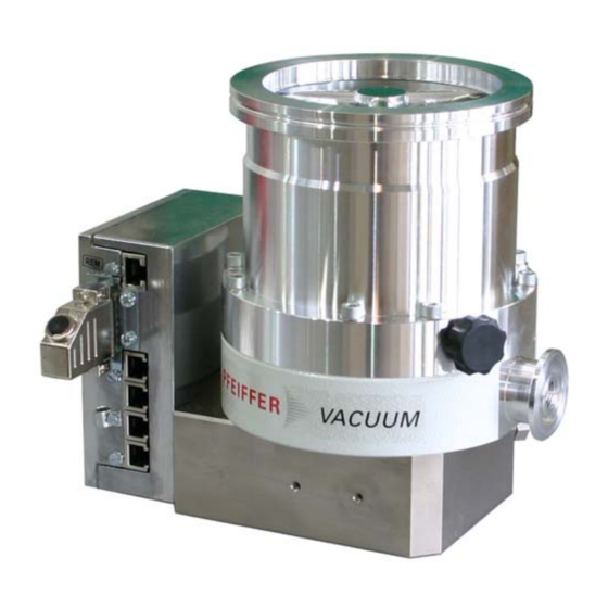
Product description High vacuum flange Electronic drive unit TC 600 Venting screw 20a Fore-vacuum flange Remote plug Fig. 2: View of CompactTurbo™ TMH 261 NOTE Observe the connection instructions! On delivery turbopumps with TC 600 are set up for operations with "Remote Control". Before operating with DCU, HPU or PC the 15-pole D-Sub connector (remote plug) must be removed from the TC 600. -
Page 9: Installation
Only use original components for the installation. NOTE Installation and operation of accessories Pfeiffer Vacuum pumps can be equipped with a series of adapted accessories. The installation, operation and maintenance of connected devices are described in detail in the operating instructions of the individual components. - Page 10 Vibration damper CAUTION Danger from the pump being ripped off When a Pfeiffer Vacuum vibration damper is used, suitable safety measures must be taken to compensate for the torques in case of sudden blocking. Definitely consult with Pfeiffer Vacuum. Do not exceed the maximum permitted temperature at the vibration compensator (100°C).
- Page 11 Installation NOTE Possible damage to the pump If a pump with an ISO-K flange is fastened to a vacuum chamber with an ISO-F flange or if ISO-KF flanges are used, sudden blocking of the rotor can result in twisting despite proper installation. Installation of ISO-K For the installation of the flange connections the following components are avail- able:...
- Page 12 Installation The connection types for installation of CF to CF flange are "stud screw and pocket hole" as well as "hex screw and through hole". The following elements are re- quired: • A set of mounting material for the respective type of connection •...
-
Page 13: Connections To The Turbopump
"FV PUMP" connection of the TC 600 . Cooling Pfeiffer Vacuum turbopumps must be cooled by means of air or water cooling. • When operating the pump with more than 50 % of the maximum gas load, sealing gas must be used to ensure rotor cooling. - Page 14 Installation Electrical connection Plug the control lead of the venting valve in accordance with the accessory’s operating instructions. Select the venting mode of the venting valve via the DCU, HPU or serial interface RS485. Casing heating unit The turbopump and vacuum chamber can be heated to reach the final pressure more quickly.
- Page 15 Connecting the elec- The turbopumps CompactTurbo™ TMH/U 261 form a single unit with the electron- ic drive unit. For voltage supply, use only Pfeiffer Vacuum power supplies (e.g. tronic drive unit to TPS 200 or DCU 200). Use other power supplies only after consultation with Pfe-...
-
Page 16: Connecting Pfeiffer Vacuum Display And Control Units Or Pc
Installation 5.5 Connecting Pfeiffer Vacuum display and control units or PC NOTE Observe the connection instructions! On delivery turbopumps with TC 600 are set up for operations with "Remote Control". Before operating with DCU, HPU or PC the 15-pole D-Sub connector (remote plug) must be removed from the TC 600. -
Page 17: Connecting The Remote Control
Installation Cross-linking via the TIC 001/ connection RS485 USB/RS485-converter RS 485 CAUTION Danger of electric shock The insulation measures of the bus system are designed only for use with safety extra- low voltage. Connect only suitable devices to the bus system. The connections must be made in accordance with the specification of the inter- face RS485. - Page 18 Installation Pin Function Open (low) Closed (high) Pumping station on: the turbo- pump is driven, backing pump Pumping station Pumpstand aus control via relay box, the air cooling unit runs Heating on: the heating is swit- ched on once the rotation switchpoint is attained.
-
Page 19: Connections Diagram Tc
Installation 5.7 Connections diagram TC TC 600 TC 750 n.c. +24 VDC* / max. 200 mA (supply voltage, DCU) n.c. n.c. RS 485 RS 485+/ (DO/RI) GND* (mass connection, DCU) RS 485- / (DO/RI) n.c. +24 VDC*/max. 50 mA Venting release Motor TMP Contact current: Pumping station... -
Page 20: Operation
6 Operation NOTE Installation and operation of accessories Pfeiffer Vacuum pumps can be equipped with a series of adapted accessories. The installation, operation and maintenance of connected devices are described in detail in the operating instructions of the individual components. -
Page 21: Function Description
DCU 200. DCU or HPU Settings are possible via the RS485 on the TC 600 by using DCU, HPU or PC. Observe the following documents for operation with Pfeiffer Vacuum display and control units: • Operating instructions DCU • Operating instructions HPU 001 •... - Page 22 Operation • Settings are possible via the RS485 on the TC 600 by using DCU, HPU or PC. Turbopump motor After the pumping station is switched on and the self-test successfully completed (duration approx. 10 seconds), the turbopump is set into operation. During opera- tion, the turbopump can be switched off and on again, while the pumping station remains switched on.
- Page 23 Pumping of gases with the molecular mass ≥ 40 in the wrong gas mode can lead to destruction of the pump. Ensure the gas mode is correctly set. Contact Pfeiffer Vacuum before using gases with a greater molecular mass. Hochlauf D-C = Gas mode «0»...
-
Page 24: Monitoring Of The Operation Conditions
Basic information for the rapid venting Venting of the vacuum chamber in two steps. Ask for details on individual solutions from Pfeiffer Vacuum. Vent for 20 seconds at a rate of pressure rise of max. 15 mbar/s. – The valve cross section for the venting rate of 15 mbar/s must be adapted to... -
Page 25: Maintenance / Replacement
Maintenance / replacement – For small vacuum chambers, use the Pfeiffer Vacuum TVF 005 venting valve. Then vent with an additional venting valve of any desired size. 7 Maintenance / replacement WARNING Contamination of parts and operating fluid by pumped media is possible. - Page 26 Maintenance / replacement NOTE Lubricant filling The lubricant reservoir is sufficiently filled with TL 011 lubricant. Do not add additional lubricant. Standard version Turn off the vacuum pump, vent to atmospheric pressure and allow to cool, if necessary. Remove the vacuum pump from the system, if necessary. Close the flange openings by using the original protective covers.
- Page 27 Felt washer in the lubricant reservoir packet The felt washer in the operating fluid reservoir is necessary only for special service work and is replaced by Pfeiffer Vacuum Service. Remove impurities from the turbopump and the end cover with a clean, lint-free cloth.
-
Page 28: Replacing The Electronic Drive Unit
Maintenance / replacement 7.3 Replacing the electronic drive unit WARNING Danger of electric shock Even after mains power is switched off, the subsequently running turbopump delivers voltages > 50 V . There is a danger of electric shock when touching open contacts eff. -
Page 29: Decommissioning
Check turbopump for contamination and moisture. Clean the turbopump externally with a lint-free cloth and little industrial alcohol. If necessary, have Pfeiffer Vacuum Service clean the turbopump completely. If necessary, have the bearings replaced. Take into account the total running time. -
Page 30: Malfunctions
Red LED on the TC 600 is flashing Check partial mains voltage – Power failure Check partial mains voltage for earthing Check mains power supply to the power ad- apter If no Pfeiffer Vacuum control panel is available, please contact Pfeiffer Vacuum Service... -
Page 31: Service
Service 10 Service Pfeiffer Vacuum offers first-class service! • Operating fluid and bearing change on the spot by Pfeiffer Vacuum FieldService • Maintenance / repair in the nearby ServiceCenter or ServicePoint • Fast replacement with exchange products in mint condition •... -
Page 32: Spare Parts Tmh/U 261
Spare parts TMH/U 261 11 Spare parts TMH/U 261 Item Designation Size Order Number Notes Pieces Order Qty End cover M40 x 1 PM 003 619 A Lubricant reservoir PM 063 265 -T incl. O-ring incl. 8 x Porex rod (7a), O- Lubricant reservoir ("Y") PM 053 266 -T ring, felt washer... -
Page 33: Accessories
DN 100 CF-F PM 006 488 -X PWM box rotation speed control 10 - 30 V DC PM 051 028 -U PM 0563 BN Pfeiffer Vacuum protocol RS232/RS485 PM 0488 BN interface protocol TIC 001 Interface converter RS232 in RS485... -
Page 34: Technical Data
Technical data 13 Technical data Parameter TMH 261 P TMU 261 P TMH 261 YP TMU 261 YP Flange (in) DN 100 ISO-K DN 100 CF-F Flange (out) DN 25 ISO-KF / G 1/4" DN 25 ISO-KF / G 1/4" Venting connection G 1/8"... -
Page 35: Dimension Diagrams
Technical data 13.1 Dimension diagrams 113.5 113.5 DN 25 ISO-KF DN 25 ISO-KF G1/8" G1/8" 104.2 104.2 Ø138.5 Ø138.5 DN 100 ISO-K Ø119 DN 100 CF-F Ø119 Fig. 12: TMH 261 P / YP, DN 100 ISO-K Fig. 13: TMU 261 P / YP, DN 100 CF-F... -
Page 36: Manufacturer's Declaration
In addition, the product cited below satisfies all relevant provisions of EC direc- tive "Electromagnetic Compatibility" 2004/108/EC . The agent responsible for compiling the technical documentation is Mr. Jörg Stanzel, Pfeiffer Vacuum GmbH, Berliner Straße 43, 35614 Aßlar. TMH 261 / TMU 261 Guidelines, harmonised standards and national standards and specifications... - Page 37 Roots pumps Dry compressing pumps Leak detectors Valves Components and feedthroughs Vacuum measurement Gas analysis System engineering Service Pfeiffer Vacuum Technology AG · Headquarters/Germany Tel. +49-(0) 64 41-8 02-0 · Fax +49-(0) 64 41-8 02-2 02 · info@pfeiffer-vacuum.de · www.pfeiffer-vacuum.net...
Need help?
Do you have a question about the Compact Turbo TurboDrag TMH 261 and is the answer not in the manual?
Questions and answers