
Related Manuals for Pfeiffer Vacuum TMH 521


Summary of Contents for Pfeiffer Vacuum TMH 521
- Page 1 Betriebsanleitung • Operating Instructions Translation of the Original Operating Instructions Compact Turbo TurboDrag Pump TMH 521 TMU 521...
-
Page 2: Table Of Contents
Connections to the turbopump ......14 Connecting Pfeiffer Vacuum display and control units or PC ..17 Connecting the remote control . -
Page 3: About This Manual
1 About this manual 1.1 Validity This operating manual is for customers of Pfeiffer Vacuum. It describes the func- tioning of the designated product and provides the most important information for safe use of the unit. The description follows applicable EU guidelines. All informa- tion provided in this operating manual refer to the current state of the product's de- velopment. - Page 4 About this manual Piktograph Prohibition of an action or activity in connection with a definitions source of danger, the disregarding of which may result in serious accidents. Warning of a displayed source of danger in connection with operation of the unit or equipment. Command to perform an action or task associated with a source of danger, the disregarding of which may result in serious accidents.
-
Page 5: Safety
• Only operate the turbopump with a prooved backing pump. • Only operate the turbopump with TC by a specified Pfeiffer Vacuum power sup- ply. The use of other power units than the intended, is only permitted after co- sultation with Pfeiffer Vacuum. -
Page 6: Improper Use
• The connection to a power supply with earthing of a direct voltage pole. • The use of accessories, which are not named in this manual or not authorised by Pfeiffer Vacuum. 3 Transport and storage 3.1 Transport Reuse the transport container. -
Page 7: Product Description
Germany Fig. 1: Example for a rating plate Standard version Turbopumps without a property, which concernes to the installation orientation will be characterized as standard version in the following (e.g. TMH 521 P). Pump features Characteristics TMH 521 TMU 521... -
Page 8: Range Of Application
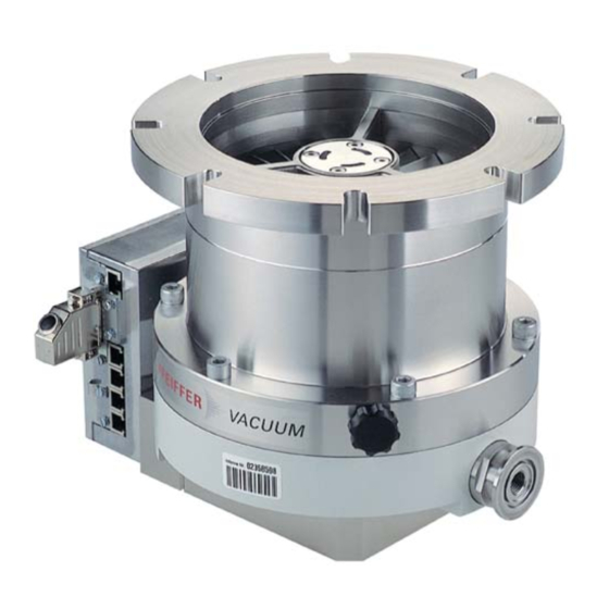
12 Venting screw 15 High vacuum flange 39 Fore-vacuum flange 98 Remote plug Fig. 2: View of CompactTurbo™ TMH 521 P NOTE Observe the connection instructions! On delivery turbopumps with TC 600 are set up for operations with "Remote Control". -
Page 9: Installation
Only use original components for the installation. NOTE Installation and operation of accessories Pfeiffer Vacuum pumps can be equipped with a series of adapted accessories. The installation, operation and maintenance of connected devices are described in detail in the operating instructions of the individual components. - Page 10 Installation Splinter shield and The installation of a Pfeiffer Vacuum centering ring with splinter shield or protec- tion screen in the high vacuum flange protects the turbopump against foreign bod- protection screen ies coming from the recipient. The volume flow rate is reduced as followed.
- Page 11 The com- ponents for installing the turbo pumps are special designs of Pfeiffer Vacuum. Ob- serve the minimum strength of 170 N/mm for the flange material.
- Page 12 Installation Connection nominal diameter Designation Ordering No. Centering ring (coated) PM 016 210-U Centering ring (coated) with PM 016 211-U splinter shield Centering ring (coated) with PM 016 212-U DN 100 ISO-F protective screen Hexagon screw (use 8 pieces) N 3024 428 1C Stud screw with nut (use 8 N 3169 428 2C pieces each, for clearence hole...
- Page 13 Installation Installation of CF-F flanges NOTE Preservation of sealing capacity Observe the following to preserve sealing capacity: Touch seals only with gloves. Make sure sealing lips are undamaged. The connection types for installation of CF-F to CF-F flange are "stud screw and pocket hole"...
-
Page 14: Connections To The Turbopump
"FV PUMP" connection of the TC 600 . Cooling Pfeiffer Vacuum turbopumps must be cooled by means of air or water cooling. • When operating the pump with more than 50 % of the maximum gas load, sealing gas must be used to ensure rotor cooling. - Page 15 Installation Connect air cooling for the corresponding pump type in accordance with the ac- cessory's operating manual. Connect water cooling for the corresponding pump type in accordance with the accessory's operating manual. Venting valve The TVF 005 venting valve is used for automatic flooding in case of shut-down or power failure.
- Page 16 Connecting the elec- The turbopumps CompactTurbo™ TMH/U 521 form a single unit with the electron- ic drive unit. For voltage supply, use only Pfeiffer Vacuum power supplies (e.g. tronic drive unit to TPS 300 or DCU 300). Use other power supplies only after consultation with Pfe-...
-
Page 17: Connecting Pfeiffer Vacuum Display And Control Units Or Pc
After operating voltage is applied, the TC 600 performs a self-test to check the sup- ply voltage. The supply voltage for the turbopumps TMH/U 521 is 72 VDC ± 5% in accordance with standard EN 60 742. 5.5 Connecting Pfeiffer Vacuum display and control units or PC NOTE Observe the connection instructions! On delivery turbopumps with TC 600 are set up for operations with "Remote Control". -
Page 18: Connecting The Remote Control
Installation Designation Value Start bits Stop bits 1..2 Assignement not connected +24 V output ladable with ≤ 210 mA not connected 1 ..8 not connected RS485: D+ RS485: D- not connected Cross-linking via the TIC 001/ connection RS485 USB/RS485-converter RS 485 CAUTION Danger of electric shock... - Page 19 Installation Connect the shielding on the plug side for the TC 600 to the TC housing. Pin assignment and Reference voltage function of the re- Pin Function mote plug +24 V Reference voltage level for all remote in and outputs Ground Ground potential for all remote in- and putputs Inputs...
-
Page 20: Connections Diagram Tc
Installation 5.7 Connections diagram TC TC 600 TC 750 n.c. +24 VDC* / max. 200 mA (supply voltage, DCU) n.c. n.c. RS 485 RS 485+/ (DO/RI) GND* (mass connection, DCU) RS 485- / (DO/RI) n.c. +24 VDC*/max. 50 mA Venting release Motor TMP Contact current: Pumping station... -
Page 21: Operation
6.2 Operation modes The following operation modes are available: • Operation without operating panel • Operation via remote control unit • Operation via RS485 with Pfeiffer Vacuum display and control units or PC 6.3 Function description NOTE Installation and operation of accessories Pfeiffer Vacuum pumps can be equipped with a series of adapted accessories. - Page 22 DCU 300. DCU or HPU Settings are possible via the RS485 on the TC 600 by using DCU, HPU or PC. Observe the following documents for operation with Pfeiffer Vacuum display and control units: • Operating instructions DCU • Operating instructions HPU 001 •...
- Page 23 Operation After the rotation speed switchpoint is reached, the heating is switched on and switched off again when this point is fallen below. A purge gas valve can optionally be triggered here. Reset The heating input is assigned a dual function ((siehe S. 18, Kap. 5.6), Point 5 ”Re- set“).
-
Page 24: Montioring Of The Operation Conditions
Pumping of gases with the molecular mass ≥ 40 in the wrong gas mode can lead to destruction of the pump. Ensure the gas mode is correctly set. Contact Pfeiffer Vacuum before using gases with a greater molecular mass. Hochlauf D-C = Gas mode «0»... -
Page 25: Switching Off And Venting
– The valve cross section for the venting rate of 15 mbar/s must be adapted to the size of the vacuum chamber. – For small vacuum chambers, use the Pfeiffer Vacuum TVF 005 venting valve. Then vent with an additional venting valve of any desired size. -
Page 26: Maintenance / Replacement
Decontaminate affected parts before carrying out maintenance work. NOTE Disclaimer of liability Pfeiffer Vacuum accepts no liability for personal injury or material damage, losses or operating malfunctions due to improperly performed maintenance. The liability and warranty entitlement expires. 7.1 Maintenance intervals and responsibilities •... - Page 27 Maintenance / replacement Standard version Turn off the vacuum pump, vent to atmospheric pressure and allow to cool, if necessary. Remove the vacuum pump from the system, if necessary. Close the flange openings by using the original protective covers. Turn the turbopump over onto the closed high vacuum flange. Screw out the end cover on the bottom of the turbopump with special tool E.
- Page 28 Felt washer in the lubricant reservoir packet The felt washer in the operating fluid reservoir is necessary only for special service work and is replaced by Pfeiffer Vacuum Service. Remove impurities from the turbopump and the end cover with a clean, lint-free cloth.
-
Page 29: Replacing The Electronic Drive Unit
Maintenance / replacement 7.3 Replacing the electronic drive unit WARNING Danger of electric shock Even after mains power is switched off, the subsequently running turbopump delivers voltages > 50 V . There is a danger of electric shock when touching open contacts eff. -
Page 30: Decommissioning
Check turbopump for contamination and moisture. Clean the turbopump externally with a lint-free cloth and little industrial alcohol. If necessary, have Pfeiffer Vacuum Service clean the turbopump completely. If necessary, have the bearings replaced. Take into account the total running ti- Change the operating fluid reservoir. -
Page 31: Malfunctions
Red LED on the TC 600 is flashing Check partial mains voltage – Power failure Check partial mains voltage for earthing Check mains power supply to the power ad- apter If no Pfeiffer Vacuum control panel is available, please contact Pfeiffer Vacuum Service... -
Page 32: Service
Service 10 Service Pfeiffer Vacuum offers first-class service! • Operating fluid and bearing change on the spot by Pfeiffer Vacuum FieldService • Maintenance / repair in the nearby ServiceCenter or ServicePoint • Fast replacement with exchange products in mint condition •... -
Page 33: Spare Parts Tmh/U 521
Spare parts TMH/U 521 11 Spare parts TMH/U 521 Item Designation Size Order Number Notes Pieces Order Qty Electronic drive unit TC 600 PM C01 720 End cover M40 x 1 PM 003 619 A Lubricant reservoir PM 063 265 -T incl. -
Page 34: Accessories
DN 160 CF-F PM 006 493 -X PWM box rot. speed control 15 - 30 V DC PM 051 028 -U PM 0563 BN Pfeiffer Vacuum protocol RS232/RS485 PM 0488 BN Interface protocol TIC 001 Interface converter RS232 in RS485... -
Page 35: Technical Data
Technical data 13 Technical data DN 100 TMH 521 P TMH 521 P TMU 521 P TMH 521 YP TMH 521 YP TMU 521 YP Flange (in) DN 100 ISO-K DN 100 ISO-F DN 100 CF-F Flange (out) DN 25 ISO-KF / G 1/4"... - Page 36 Technical data DN 160 TMH 521 P TMH 521 P TMU 521 P TMH 521 YP TMH 521 YP TMU 521 YP Flange (in) DN 160 ISO-K DN 160 ISO-F DN 160 CF-F Flange (out) DN 25 ISO-KF / G 1/4"...
-
Page 37: Dimension Diagrams
Technical data 13.1 Dimension diagrams DN 25 ISO-KF DN 25 ISO-KF 122.7 122.7 DN 160 ISO-K DN 100 ISO-K Ø 208 Ø 208 DN 25 ISO-KF DN 25 ISO-KF 122.7 122.7 DN 100 CF-F DN 160 CF-F Ø 208 Ø 208 DN 25 ISO-KF DN 25 ISO-KF 122.7... - Page 38 In addition, the product cited below satisfies all relevant provisions of EC direc- tive "Electromagnetic Compatibility" 2004/108/EC . The agent responsible for compiling the technical documentation is Mr. Jörg Stanzel, Pfeiffer Vacuum GmbH, Berliner Straße 43, 35614 Aßlar. TMH 521 / TMU 521 Guidelines, harmonised standards and national standards and specifications...
-
Page 39: Manufacturer's Declaration
Roots pumps Dry compressing pumps Leak detectors Valves Components and feedthroughs Vacuum measurement Gas analysis System engineering Service Pfeiffer Vacuum Technology AG · Headquarters/Germany Tel. +49-(0) 64 41-8 02-0 · Fax +49-(0) 64 41-8 02-2 02 · info@pfeiffer-vacuum.de · www.pfeiffer-vacuum.net...
Need help?
Do you have a question about the TMH 521 and is the answer not in the manual?
Questions and answers