Pfeiffer Vacuum TurboDrag TMH 071 Y P N Operating Instructions Manual
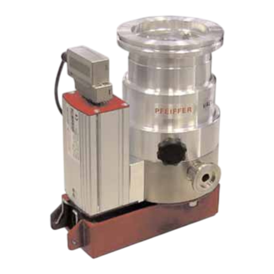
Pump with electronic drive unit tc 100 and integrated power supply
Hide thumbs
Also See for TurboDrag TMH 071 Y P N:

Related Manuals for Pfeiffer Vacuum TurboDrag TMH 071 Y P N


Summary of Contents for Pfeiffer Vacuum TurboDrag TMH 071 Y P N
- Page 1 Betriebsanleitung • Operating Instructions Translation of the Original Operating Instructions TurboDrag Pump With Electronic Drive Unit TC 100 And Integrated Power Supply TMH 071 Y P N TMU 071 Y P N...
-
Page 2: Table Of Contents
Index Page Page Safety Instructions......3 Monitoring Operations ....18 1.1. For Your Orientation ......... 3 5.1. Operations Display Via LED ......18 1.2. Pictogram Definitions ........3 5.2. Turbopump Temperature Management ..18 What To Do In Case Of Understanding The Turbopumps . -
Page 3: Safety Instructions
1. Safety Instructions ☞ Read and follow all instructions in this manual. 1.1. For Your Orientation ☞ Inform yourself regarding: I I n n s s t t r r u u c c t t i i o o n n i i n n t t h h e e t t e e x x t t –... -
Page 4: Understanding The Turbopumps
2. Understanding The Turbopumps 2.1. Main Features Proper Use Turbopumps TMH/TMU 071/071 Y P N and electronic form an – The Turbomolecular Pumps may only be used for the unit. Voltage is supplied by the mains power (mains cable see purpose of generating vacuum. -
Page 5: Differences Between The Pump Types
2.2. Differences Between The Pump Types 2.3. Scope Of Delivery Turbomolekular pump with: Feature TMH 071 Y P N TMU 071 Y P N - Electronic Drive Unit TC 100, High vacuum flange ISO-K CF-F - Power Supply OPS 070, High vacuum seal Elastomer seal Metal... -
Page 6: Installation
Pfeiffer Vacuum represen- tatives. Use a Pfeiffer Vacuum splinter shield or protective screen The use of a Pfeiffer Vacuum splinter shield or protective – For operating the turbopump air cooling is necessary screen in the high vacuum flange protects the turbopump (please see Section 11. - Page 7 Connecting via a Pfeiffer Vacuum vibration compensator ISO-K flange with ISO-F flange The high vacuum side can be flanged onto the vacuum cham- ber either directly or via a Pfeiffer Vacuum vibration compen- If the pumps are secured with an ISO-K flange WARNING sator (see Section 11.
- Page 8 CF-F flange Hexagon screw and clearance hole ➡ If used: Insert the splinter shield and protective screen in Applications for installing an CF-F to an CF-F flange are “Stud screw with blind hole” and “Hexagon screw and clearance the high vacuum flange with the clamping lugs downward hole”.
-
Page 9: Connecting The Fore-Vacuum Side
Directly flanging the pump 3.3. Connecting The Fore-Vacuum Side The high vacuum flange of the turbopumps in “Y” version can Vacuum pressure ≤ 10 mbar Backing pump: be fitted in all positions. Recommendation: Oil-Free Diaphragm Pump or Rotary Vane Vacuum Pumps from the Pfeiffer With horizontal pump installation and oil-sealed backing Vacuum range (note installation position, pumps (e.g. -
Page 10: Connecting The Cooling Unit
3.4. Connecting The Cooling Unit 3.6. Connecting The Electronic The Turbopumps TMH/TMU 071 Y P N must be air cooled. Turbopump, Electronic Drive Unit TC 100 and PLEASE NOTE Air cooling may only be used where the ambient temperature Integrated Power Supply are fixed together and is <... -
Page 11: Installing The Display And Operating Unit Dcu 001 Or Hpu 001
3.7. Installing The Display And Operating Unit DCU 001 or HPU 001 The connection of an Operating And Display Control Unit DCU 001 or HPU 001 is available with the Connection Box TCS 010 (see Section 11. Accessories). ➡ Before connecting a DCU/HPU remove the jumpers (see Sec. -
Page 12: Remote Control Unit
3.9. Remote Control Unit When connecting supply voltage, the CAUTION turbopump is started. Remote control options for various functions are available via O O n n d d e e l l i i v v e e r r y y : : connection plug X3 (Pin 2 –... -
Page 13: Connecting The Serial Interface Rs 485
3.10. Connecting Serial Interface Connecting The RS 485 RS 485 Connection to a fixed bus system The connection of the Operating And Control Unit DCU 001 or ➡ Connect all units with D+ (Pin 13/X3) and D- (Pin 14/X3) on HPU 001 is possible via the Connection Box TCS 010 (please the bus. -
Page 14: Connections Diagram
3.11. Connection Diagram External connection TC 100 Remote/Local Remote/Local Accessory 1 Accessory 1 Accessory 2 venting valve Accessory 2 cooling unit Pumping station relay Pumping station Standby/Reset Standby/Reset 24 VDC* 24 VDC* venting valve cooling unit relay Accessory output 1 24 VDC/max. -
Page 15: Operations
4. Operations 4.1. Before Switching ON Local/Remote Sections 4.1. to 4.3. relate only to pump operations in the (Pin 2/X3) condition on delivery without display and operating unit. This input is used to determine whether the control should be effected via remote control inputs or Serial Interface RS 485 Turbopump rotors turn at great speed. -
Page 16: Switch Outputs
Switch Outputs 4.4. Gas Type Dependent Operations (Pin 8/X3 And Pin 9/X3) Where high level gas loads and rotation speeds are involved, The switch outputs 1 and 2 can be loaded with maximum the resulting friction subjects the rotor to the effect of great 24 V/50 mA per output. -
Page 17: Switching Off And Venting
If the pump has been shut down for 3 3 y y e e a a r r s s , the PLEASE NOTE bearing must be changed (please contact Pfeiffer Vacuum Service). 4.7. Operations With The DCU 001 or HPU 001... -
Page 18: Monitoring Operations
5. Monitoring Operations 5.1. Operations Display Via LED 5.2. Turbopump Temperature Management Certain operations modes of the turbopump and the TC 100 can be ascertained via the two integrated LEDs located on Where impermissible motor temperatures are involved or the the front panel of the TC 100. -
Page 19: What To Do In Case Of Breakdowns
• Enter 1500 Hz for parameter 777 (Parameter 777) (see operating instruction PM 0547 BN “Pumping Operations With DCU”). If there is no DCU/HPU available contact Pfeiffer Vacuum Service. 1) Without a DCU or HPU inform Pfeiffer Vacuum Service to check the cause of trouble. -
Page 20: Maintenance/Replacement
Where extreme operating conditions or unclean processes are involved, the replacement interval should be checked with your Pfeiffer Vacuum Service Center. You can change the integrated Power Supply, the Electronic Drive Unit TC 100 and the lubricant reservoir yourself (please see Section 7.1., 7.2., 7.3.). -
Page 21: Replacing The Electronic Driveunit Tc 100
➡ Remove the Electronic Drive Unit TC 100 (8) from the 7.2. Replacing The Electronic DriveUnit turbopump. TC 100 Please take into account that after replacing PLEASE NOTE the TC 100 the following parameters must be modified with the use of DCU 001, HPU 001 or serial interface before operation the pump: [ [ P P : : 0 0 2 2 9 9 ] ] «OpMode Drv»... -
Page 22: Replacing The Lubricant Reservoir
Where extreme operating conditions or unclean processes are involved, the replacement interval should be checked with your Pfeiffer Vacuum Service Center. ➡ Switch off the turbopump, vent to atmospheric pressure and remove the integrated Power Supply as described under Section 7.1. -
Page 23: Service
➡ A copy of the completed declaration must accompany the unit; any additional copies must be sent to your local Pfeiffer Vacuum Service Center. Please get in touch with your local Pfeiffer Vacuum represen- tatives if there are any questions regarding contamination. -
Page 24: Technical Data
9. Technical Data F F e e a a t t u u r r e e U U n n i i t t T T M M H H 0 0 7 7 1 1 Y Y P P N N T T M M H H 0 0 7 7 1 1 Y Y P P N N T T M M U U 0 0 7 7 1 1 Y Y P P N N Connection nominal diameter... -
Page 25: Dimensions Diagram
9.1. Dimensions Diagram TMH 071 Y P N DN 63 ISO-K; DN 40 ISO-KF 97.5 DN 16 ISO-KF DN 40 ISO-KF DN 63 ISO-K Ø 96 Values in parentheses apply to pumps DN 63 ISO-K... - Page 26 TMU 071 Y P N DN 63 CF-F 97.5 DN 16 ISO-KF DN 63 CF-F Ø 96...
-
Page 27: Spare Parts
10. Spare Parts Pos. Description Pieces Size Number Comments Ordering Quantity Spare Parts TMH/TMU 071 Y P N Electronic Drive Unit TC 100 PM C01 692 A see Section 7.2. O-ring 38x3 P 4070 972 PP Lubricant reservoir (with o-ring 93) PM 103 794 -T see Section 7.3. -
Page 28: Accessories
11. Accessories Description Size Number Comments/ Order Quantity Operating Instructions Components for cooling Air cooling 24 V DC PM Z01 253 A PM 0543 BN Components for venting Venting Valve TVF 005, without current closed 24 V DC PM Z01 135 PM 0507 BN Drying Unit TTV 001 PM Z00 121... -
Page 29: Declaration Of Contamination
Declaration of Contamination of Vacuum Equipment and Components The repair and/or service of vacuum components will only be The manufacturer could refuse to accept any equipment carried out if a correctly completed declaration has been without a declaration. submitted. Non-completion will result in delay. This declaration can only be completed and signed by authorised and qualified staff: 1. -
Page 30: Declaration Of Conformity
"Electromagnetic Compatibility" 2004/108/EC . The agent responsible for compiling the technical documentation is Mr. Jörg Stanzel, Pfeiffer Vacuum GmbH, Berliner Straße 43, 35614 Aßlar. TMH 071 Y P N / TMU 071 Y P N Guidelines, harmonised standards and national standards and specifications... - Page 31 Roots pumps Dry compressing pumps Leak detectors Valves Components and feedthroughs Vacuum measurement Gas analysis System engineering Service Pfeiffer Vacuum Technology AG · Headquarters/Germany Tel. +49-(0) 64 41-8 02-0 · Fax +49-(0) 64 41-8 02-2 02 · info@pfeiffer-vacuum.de · www.pfeiffer-vacuum.net...
Need help?
Do you have a question about the TurboDrag TMH 071 Y P N and is the answer not in the manual?
Questions and answers