
Related Manuals for Pfeiffer Vacuum TMH 071


Summary of Contents for Pfeiffer Vacuum TMH 071
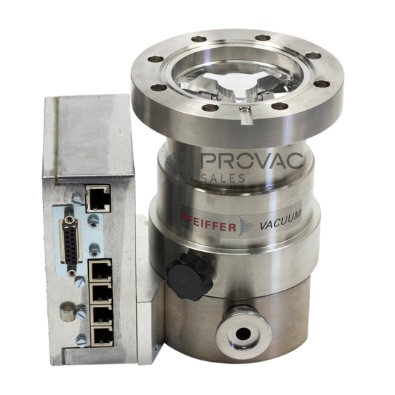
- Page 1 Betriebsanleitung • Operating Instructions Translation of the Original Operating Instructions TurboDrag Pump with Electronic Drive Unit TC 600 TMH 071 TMU 071...
-
Page 2: Table Of Contents
Manufacturer’s Declaration .. (last page) 3.8. Connecting The Electronic Drive Unit TC 600 11 3.9. Installing The Power Supply ......11 3.10. Installation Of Pfeiffer Vacuum ...... 12 Display And Control Units Connection ............. 12 3.11. Connecting The RS 485 ........ 12 3.12. -
Page 3: Safety Instructions
1. Safety Instructions 1.1. For Your Orientation ☞ Read and follow all instructions in this manual. ☞ Inform yourself regarding: Instruction in the text – Hazards which can be caused by the pump; ➡ Working instruction: here, you have to do something. –... -
Page 4: Understanding The Pumps
2.1. Main Features Ambient conditions The turbomolecular pump needs to be installed in compliance Turbopumps TMH 071 / TMU 071 with the TC 600 form a with the following ambient conditions: complete unit. Voltage is supplied by the power unit (see ”Accessories”). -
Page 5: Proper Use
Proper Use 2.2. Differences Between The Pump Types – The Turbomolecular Pumps TMH 071 / TMU 071 may only be used for the purpose of generating vacuum. Feature TMH 071 TMU 071 – The turbopumps may only be used to pump those media against which they are chemically resistant. -
Page 6: Installation
(please see rating plate, for In case the rotor blocks suddenly, torque levels example TMH 071 Y P) may be fitted in all posi- WARNING up to 8 8 2 2 0 0 N N m m can occur which need to be ab- tions. -
Page 7: Installing The High Vacuum Flange
Otherwise the turbomolecular Claw grip (ISO-K with ISO-F) pump may twist or tear off. The clamps, bolts, nuts and ISO-K flansch centering rings are special designs from Pfeiffer Vacuum Claw grip – The minimum strength of 170 N/mm of the flange material... -
Page 8: Directly Flanging The Pump
(please see rating plate, e.g. Protective screen PM 016 333 TMH 071 Y P) may be fitted in any positions. Turbopumps in standard version (without “Y” 1) supplied pieces on the rating plate) can be flanged onto the vacuum chamber vertically (0°) up to an angle... -
Page 9: Connecting The Fore-Vacuum Side
3.4. Connecting The Cooling Unit turbopump must be aligned vertically downwards (maximum deviation ±20°), otherwise the turbopump could become dirty. Turbopumps TMH 071 / TMU 071 can optionally be provided with enhanced convection cooling, air cooling or water Installation position with oil-sealed backing pump cooling. -
Page 10: Connecting The Venting Valve
3.5. Connecting The Venting Valve The temperature of the high vacuum flange must CAUTION not exceed 120 °C. The venting valve TVF 005 (accessory) provides automatic venting in the event of a power failure and switching off. Fitting the venting valve ➡... -
Page 11: Connecting The Electronic Drive Unit Tc 600
TC 600 voltage. The supply voltage for turbopumps The turbopump and the electronic drive unit TMH 071 / TMU 071 is 24 VDC ±5% in accor- PLEASE NOTE TC 600 are connected and together form a dance with EN 60 742. -
Page 12: Installation Of Pfeiffer Vacuum
3.10. Installation Of Pfeiffer Vacuum It is possible to connect an RS 232 (e.g. PC) via PLEASE NOTE a level converter (please see ”Accessories”). Display And Control Units An external display and control unit (DCU 001, DCU 100, HPU 001) or an external PC can be connected via the connection ”RS 485”... -
Page 13: Connecting The Remote Control Unit
3.12. Connecting The Remote Control Pin occupancy remote plug Unit Remote control options for various functions are provided with the connection "REMOTE" on the TC 600 via the 15-pole D-Sub-Connector. Shielded cable must be used. Shielding is on the plug side of the TC 600 connected to the TC casing. The inputs 2-6 are activated by connecting them to the + 24 V on pin 1 (active high) (please see 3.12. -
Page 14: Connections Diagram
3.13. Connections Diagram TC 600 TC 750 n.c. +24 VDC* / max. 200 mA (supply voltage, DCU) n.c. n.c. RS 485 RS 485+/ (DO/RI) GND* (mass connection, DCU) RS 485- / (DO/RI) n.c. +24 VDC*/max. 50 mA Venting release Motor TMP Contact current: Pumping station max. -
Page 15: Operations
4. Operations 4.1. Before Switching On 4.3. Operations With The Remote Control Unit Sections 4.1. to 4.3. refer only to operating the pump in its delivery status, without display and control unit. The bridges Remote control operations can be performed via the 15-pole ”venting release”, ”motor, TMP ON”... -
Page 16: Heating/Reset
Heating/Reset The connection of a relay is made between pin 10 (mass) and the respective switching output pin 8 or pin 9 (see section H H e e a a t t i i n n g g ( ( o o p p t t i i o o n n a a l l ) ) 3.13. -
Page 17: Operations With The Dcu 001/Dcu 100
The valve cross-section for a venting rate of 15 mbar/s must be compatible with the size of the vacuum chamber. Where small vacuum chambers are involved, the Pfeiffer Vacuum venting valve TVF 005 can be used for first stage venting. -
Page 18: Monitoring Operations
5. Monitoring Operations 5.1. Operations Display Via LED 5.2. Turbopump Temperature Management Certain operations modes of the turbopump and the TC 600 can be ascertained via the two integrated LEDs located on Where impermissible motor temperatures are involved or the the front panel of the TC 600. -
Page 19: What To Do In Case Of
• Enter 1500 Hz for parameter 777 (Parameter 777) (see operating instruction PM 0547 BN “Pumping Operations With DCU”). If there is no DCU/HPU available contact Pfeiffer Vacuum Service . 1) Without a DCU or HPU inform Pfeiffer Vacuum Service to check the cause of trouble. -
Page 20: Maintenance / Exchange
Pfeiffer Vacuum Service Center. You can change the electronic drive unit TC 600 and the lubri- cant reservoir yourself. Please contact your Pfeiffer Vacuum Service for all other maintenance and service work. Apply no mechanical stress to the electronic CAUTION drive unit TC 600. -
Page 21: Replacing The Lubricant Reservoir
The lubricant reservoir should be replaced at least every three years. Where extreme operating conditions or unclean processes are involved, the replacement interval should be checked with Pfeiffer Vacuum Service. The procedure for the replacement of the CAUTION lubricant reservoir depends on the turbopump type. -
Page 22: Y"-Version (Mounting In Any Orientation)
“Y”-Version ➡ Remove the Porex rods 89 (eight pieces) with tweezers. (Mounting In Any Orientation) The following instructions are only valid for CAUTION turbopump types with the properties abbre- veation “Y” on the rating plate. Both the lubricant reservoir 92 and the Porex WARNING rods 89 can contain toxic substances from the media being pumped. -
Page 23: Service
Contaminated vacuum pumps Units which are microbiologically, explosively or radioactively • Lubricant- and bearing exchange on the spot by Pfeiffer contaminated will not be accepted by Pfeiffer Vacuum as a Vacuum field service matter of principle. Hazardous substances are substances •... -
Page 24: Technical Data
F F e e a a t t u u r r e e U U n n i i t t TMH 071 P TMH 071 P TMU 071 P TMH 071 Y P TMH 071 Y P TMU 071 Y P Connection nominal diameter Inlet... -
Page 25: Dimensions Diagram
9.1. Dimensions Diagram TMH 071 P / TMU 071 P... -
Page 26: Spare Parts
10. Spare Parts Pos. Description Pieces Size Number Comments Ordering Quantity Spare parts TMH 071 / TMU 071 Rubber foot P 3695 700 ZD Electronic drive unit TC 600 PM C01 720 Locking cover PM 083 021 -X O-ring 68 x 3... -
Page 27: Accessories
11. Accessories D D e e s s c c r r i i p p t t i i o o n n S S i i z z e e N N u u m m b b e e r r C C o o m m m m e e n n t t s s / / O O r r d d e e r r Q Q u u a a n n t t i i t t y y O O p p e e r r a a t t i i n n g g I I n n s s t t r r u u c c t t i i o o n n s s... -
Page 28: Declaration Of Contamination
Declaration of Contamination of Vacuum Equipment and Components The repair and/or service of vacuum components will only be The manufacturer could refuse to accept any equipment carried out if a correctly completed declaration has been without a declaration. submitted. Non-completion will result in delay. This declaration can only be completed and signed by authorised and qualified staff: 1. -
Page 29: Declaration Of Conformity
In addition, the product cited below satisfies all relevant provisions of EC direc- tive "Electromagnetic Compatibility" 2004/108/EC . The agent responsible for compiling the technical documentation is Mr. Jörg Stanzel, Pfeiffer Vacuum GmbH, Berliner Straße 43, 35614 Aßlar. TMH 071 / TMU 071 Guidelines, harmonised standards and national standards and specifications... -
Page 30: Www.pfeiffer-Vacuum.net
Roots pumps Dry compressing pumps Leak detectors Valves Components and feedthroughs Vacuum measurement Gas analysis System engineering Service Pfeiffer Vacuum Technology AG · Headquarters/Germany Tel. +49-(0) 64 41-8 02-0 · Fax +49-(0) 64 41-8 02-2 02 · info@pfeiffer-vacuum.de · www.pfeiffer-vacuum.net...
Need help?
Do you have a question about the TMH 071 and is the answer not in the manual?
Questions and answers