Table of Contents
Advertisement
Quick Links
R12-17...L120-11
Model: E25
Assembly and Operating Instructions
en
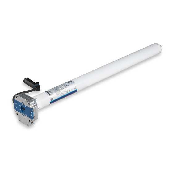
Tubular drives with crank handle activation for roller
shutters
Important information for:
• Fitters / • Electricians / • Users
Please forward accordingly!
These instructions must be kept safe for future reference.
2010 301 230 0c 12/07/2022
Becker-Antriebe GmbH
Friedrich-Ebert-Straße 2-4
35764 Sinn/Germany
www.becker-antriebe.com
Advertisement
Table of Contents

Subscribe to Our Youtube Channel
Related Manuals for Becker R12-17-E25


Summary of Contents for Becker R12-17-E25
- Page 1 Tubular drives with crank handle activation for roller shutters Important information for: • Fitters / • Electricians / • Users Please forward accordingly! These instructions must be kept safe for future reference. 2010 301 230 0c 12/07/2022 Becker-Antriebe GmbH Friedrich-Ebert-Straße 2-4 35764 Sinn/Germany www.becker-antriebe.com...
-
Page 2: Table Of Contents
Table of contents General .................................... 3 Warranty ..................................... 3 Safety instructions ................................ 4 Instructions for the user.............................. 4 Instructions for installation and commissioning........................ 4 Intended use .................................. 6 Drive version with angled plug ............................... 6 Assembly .................................... 7 Adjusting the limit positions with a rotary switch or a locking button .................. 10 Deleting the limit positions with a rotary switch or a locking button .................. -
Page 3: General
General These tubular drives are high-quality products with the following features: • Optimised for roller shutter operation • Convenient manual control in the event of power failure • Automatic detection of limit positions thanks to intelligent electronic system with stop systems •... -
Page 4: Safety Instructions
Safety instructions The following safety instructions and warnings are intended to avert hazards and to prevent property damage and personal injury. Instructions for the user General information • The drive must be disconnected from its power source during cleaning and maintenance and when re- placing parts. - Page 5 • If the drive is used for shading solutions in a specially marked area (e.g., escape routes, hazard zones, safety areas), compliance with all applicable regulations and standards must be ensured. • Once the drive has been installed, the fitter must mark the used tubular drive in the “Technical data” chapter and make a note of the installation position.
-
Page 6: Intended Use
Intended use The type of tubular drive described in these instructions is intended solely for the operation of roller shutter systems with fixed stops in both limit positions using rigid shaft connectors. The crank handle is intended to be used for convenient manual operation only in the event of a power failure. -
Page 7: Assembly
Disassembling the plug-in connecting cable for tubular drives with angled plug Caution Prior to disassembly, the power supply to the connecting cable must be disconnected. Insert a suitable flathead screwdriver right into the recess of the locating latch, so that the latch releases the locating lug from the plug. - Page 8 Assembling and disassembling the drive adapter Fitting the ring onto the thrust ring Assembling the drive adapter with safety catch on the Disassembling the drive adapter with safety catch on the drive shaft drive shaft Assembling and disassembling the drive adapter with drive adapter safety catch or screw connection Assembling and disassembling the drive Assembling and disassembling the drive adapter with separate drive adapter...
- Page 9 Assemble the tubular drive with the relevant ring (1) and drive adapter (2). If the ring has several grooves, select the groove which is a perfect fit and push the ring (1) onto the thrust ring. Insert the tubular drive with the pre-assembled ring (1) and drive adapter (2) into the tube to achieve a form fit.
-
Page 10: Adjusting The Limit Positions With A Rotary Switch Or A Locking Button
Adjusting the limit positions with a rotary switch or a locking button Intelligent installation management Completion of installation following automatic setting of limit position "Stop" Next time the “stop” limit position is travelled to, this position will be provisionally saved as the limit position. Once the limit position has been detected at this position 3 times in a row without any problems, it will be definitively saved. -
Page 11: Setting The Limit Positions Using The Programming Unit
Setting the limit positions using the programming unit Connect the wires of the tubular drive to those of the same col- our in the programming unit for drives with electronic limit Programming button Travel button switching and switch on the power supply. Attention The programming unit is only designed for the commissioning, not for continuous opera- tion. -
Page 12: Deleting The Limit Positions Using The Programming Unit
Deleting the limit positions using the programming unit Connect the wires of the tubular drive to those of the same colour in the programming unit and switch on the power supply. Please pause for 1 sec after the last drive command before beginning the deletion se- quence. -
Page 13: Additional Function Offset Lower Limit Position
Deleting both limit positions Open/close the shading solution to a point between the limit positions. Press the programming button and keep it pressed. Then press down the travel button and keep it pressed. Now release the programming button, but continue to keep the travel button pressed. Next press the programming button again. -
Page 14: Using The Crank Handle
Using the crank handle For problem-free assembly, use mechanical and electrical accessories made by the drive manufacturer which have been tested and which are suitable for use with these drives. For 7 mm hexagonal tube The crank handle is to be used only in the event of a power failure. It must be ensured and 6 mm square tube that the limit positions are not overrun. -
Page 15: Technical Data Dia. 45
Technical data dia. 45 Tubular drive R12-17 R20-17 R30-17 R40-17 Model Type HK R Rated torque [Nm] Output speed [rpm] Limit switch range 64 revolutions Supply voltage 230 V AC / 50 Hz Connected load [W] Rated current consumption [A] 0.50 0.75 0.90 1.15 Operating mode S2 4 min Degree of protection IP 44... -
Page 16: What To Do If
What to do if...? Problem Remedy The roller shutter curtain is raised unevenly or not at all. Repair system; then re-program limit positions. Tubular drive does not reach the set limit position. Move to the opposite limit position to reference the limit posi- tions again. -
Page 17: Sample Wiring Diagram
Sample wiring diagram The assignment of the black and brown wires according to the direction of travel is de- pendent on how the drive is installed (mounted to the right or to the left). Control via one button 17 - en... -
Page 18: Declaration Of Conformity
Declaration of conformity 18 - en...
Need help?
Do you have a question about the R12-17-E25 and is the answer not in the manual?
Questions and answers